Figure 24: srp i/o module for erx-14xx models – Juniper Networks ERX Hardware 8 User Manual
Page 76
ERX 8.0.x Hardware Guide
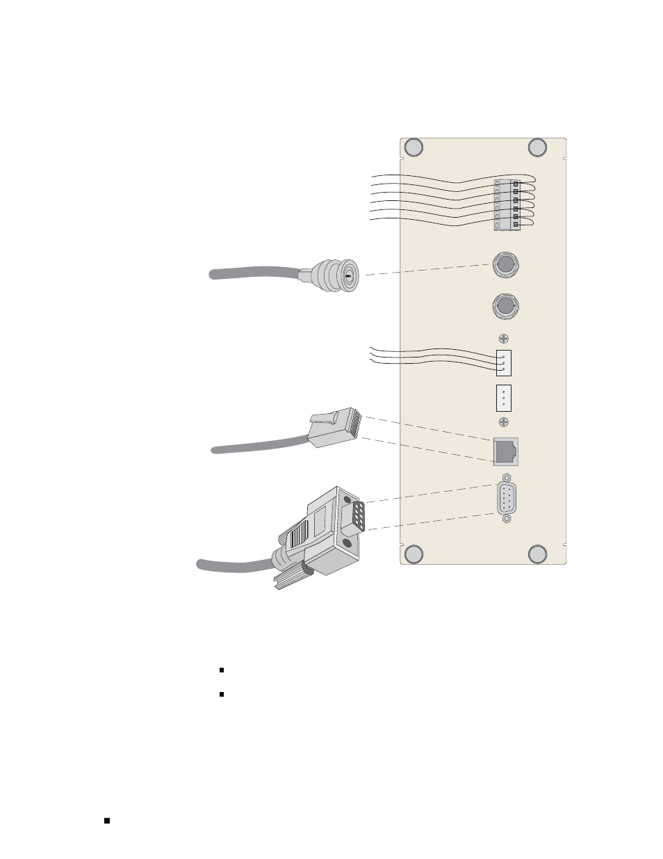
Figure 24: SRP I/O Module for ERX-14xx Models
A
T
G
R
T1 100 OHM
CLOCK IN
B
T
G
R
E1 75 OHM
CLOCK IN
+
-
+
-
+
-
ALARMS
EXTERNAL
TIMING
CONSOLE
MINOR
MAJOR
CRITICAL
10/100
BASE T
RS-232
BNC (Europe)
DB-9
RJ-45
26-AWG wire
Wire-wrap connectors
(North America, Japan)
g013750
To connect the clock source input ports:
1.
Depending on the connector type, complete one of the following tasks:
E1: Attach the BNC connector to Clock A’s external timing port.
T1: Wrap the tip wire on pin marked T of Clock A’s external timing port,
the ground wire on G pin, and the ring wire on R pin.
58
Cabling the SRP I/O Module