6 i/o connectors, 1 vga connector, 2 scsi connector – Intel SERVER BOARD SDS2 User Manual
Page 94
Connections
Intel® Server Board SDS2
Revision 1.2
Order Number: A85874-002
80
Pin
Side B
Side A
Pin
Side B
Side A
45
AD[14]
+3.3 V
91
Ground
AD[32]
46
Ground
AD[13]
92
RSV
RSV
47
AD[12]
AD[11]
93
RSV
Ground
48
AD[10]
Ground
94
Ground
RSV
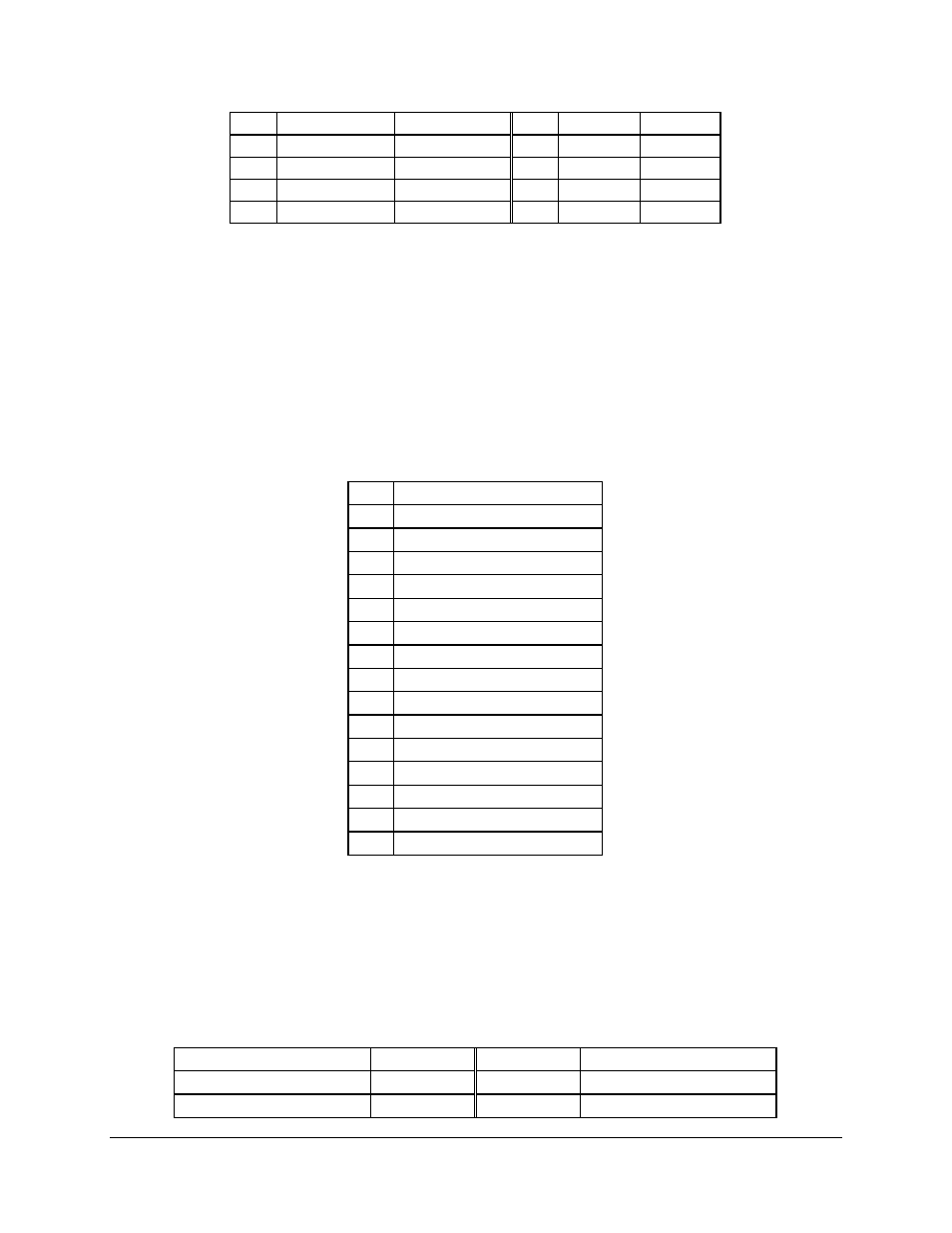
8.6 I/O Connectors
8.6.1
VGA Connector
The video connector interface is a standard VGA compatible 15-pin connector. An ATI RAGE XL
video controller with 4 MB of on-board video memory supplies video. The following table details
the pin-out of the VGA connector.
Table 63. VGA Connector Pin-out
Pin
Signal Name
1
Red (analog color signal R)
2
Green (analog color signal G)
3
Blue (analog color signal B)
4
N/C
5
GND
6
GND
7
GND
8
GND
9
Fused VCC (+5V)
10
GND
11
N/C
12
DDCDAT
13
HSYNC (horizontal sync)
14
VSYNC (vertical sync)
15
DDCCLK
8.6.2
SCSI Connector
The SDS2 Server Board provides two SCSI connectors accessible internally. The following table
details the pin-out of the 68-pin SCSI connector.
Table 64. 68-pin SCSI Connector Pin-out
Connector Contact Number
Signal Name
Signal Name
Connector Contact Number
1
+DB(12)
-DB(12)
35
2
+DB(13)
-DB(13)
36