Connections, 1 power distribution board connector – Intel SERVER BOARD SDS2 User Manual
Page 88
Connections
Intel® Server Board SDS2
Revision 1.2
Order Number: A85874-002
74
8. Connections
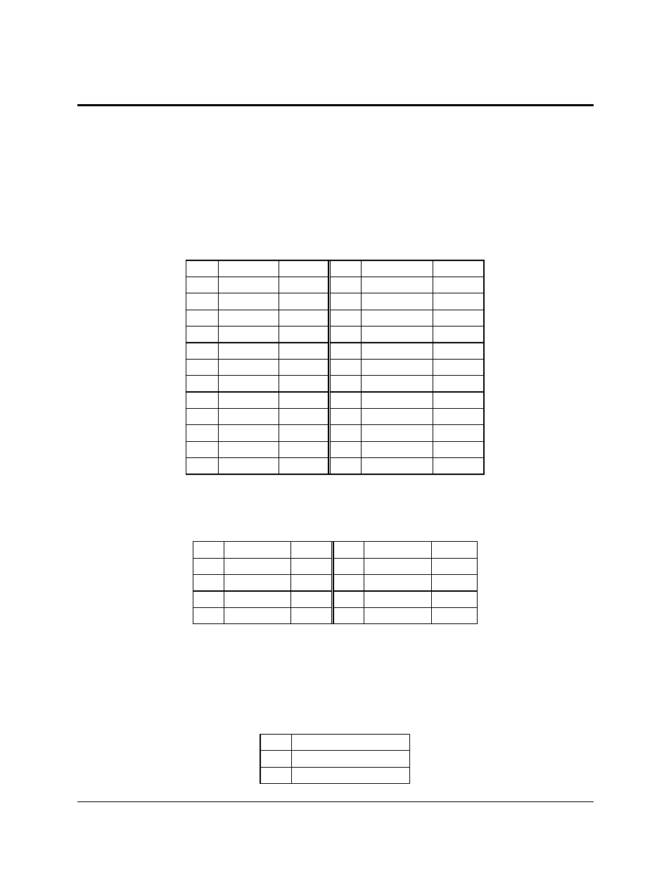
8.1 Power Distribution Board Connector
The main power supply connection is obtained using a 24-pin connector. A separate 8-pin
connector is used for the +12 V power connector dedicated to providing power to the processor.
A third 5-pin auxiliary signal connector is used to communicate with the power supply. The
following tables define the pin-outs of these connectors.
Table 52. 24-Pin Main Power Connector Pin-out
Pin
Signal
Color
Pin
Signal
Color
1
+3.3 V
Orange
13
+3.3 V
Orange
2
+3.3 V
Orange
14
-12 V
Blue
3
COM
Black
15
COM
Black
4
+5 V
Red
16
PS_ON#
Green
5
COM
Black
17
COM
Black
6
+5 V
Red
18
COM
Black
7
COM
Black
19
COM
Black
8
PWR_OK
Gray
20
RSVD_(-5 V)
White
9
5 VSB
Purple
21
+5 V
Red
10
+12 V_IO
Yellow
22
+5 V
Red
11
+12 V_IO
Yellow
23
+5 V
Red
12
+3.3 V
Orange
24
COM
Black
Table 53. 8-Pin +12 V Power Connector Pin-out
Pin
Signal
Color
Pin
Signal
Color
1
COM_CPU
Black
5
+12V_CPU
Yellow
2
COM_CPU
Black
6
+12V_CPU
Yellow
3
COM_CPU
Black
7
+12V_CPU
Yellow
4
COM_CPU
Black
8
+12V_CPU
Yellow
Note: The SDS2 server board requires a +12 V Power Connector. The board will not power on
without +12 V Power supplied to this connector.
Table 54. Aux Signal Connector Pin-out
Pin
Signal Name
1
I2C Clock
2
I2C Data