Intel SERVER BOARD SDS2 User Manual
Page 106
Jumpers
Intel® Server Board SDS2
Revision 1.2
Order Number: A85874-002
92
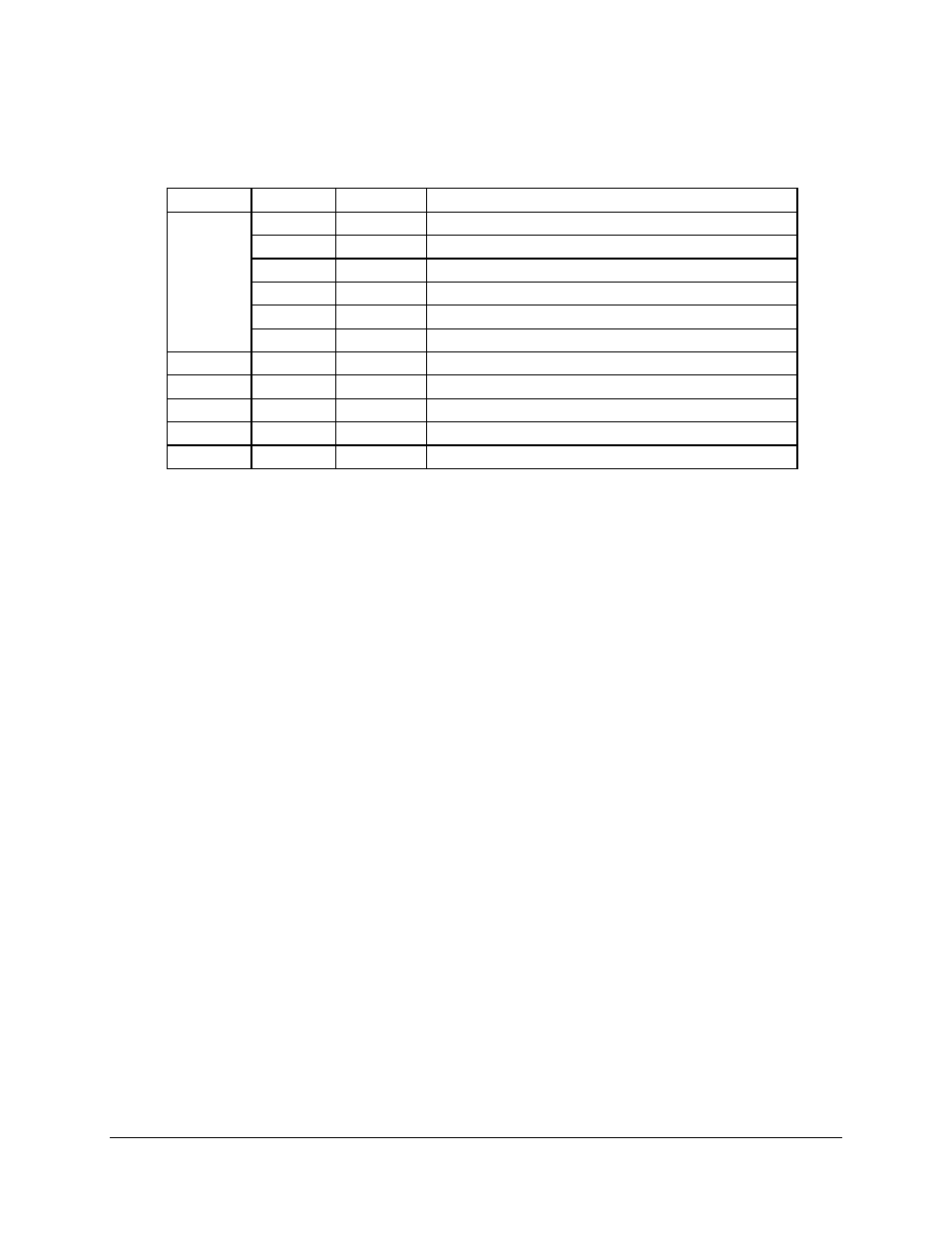
Table 80. List of Assembled Jumpers in Production
Jumper
Pins
Default
Operation
1 – 2
Open
When closed, clears CMOS during POST
3 – 4
Open
When closed, clears CMOS password
5 – 6
Open
RESERVED (Do Not Use)
7 – 8
Open
RESERVED (Do Not Use)
9 – 10
Open
When closed, forces BIOS Recovery Mode
CN42
11 – 12
Closed
SPARE jumper storage
CN46
1 – 2
Open
When closed, permits BIOS boot block to be updated
CN47
1 – 2
Open
When closed, permits BMC boot block to be updated
CN48
1 – 2
Open
When closed, disables FRB timer
CN49
1 – 2
Open
When closed, forces BMC in Update Mode
CN50
1 – 2
Closed
When closed, disables chassis intrusion sensor
9.2 Performing CMOS Clear, BIOS Recovery, and BMC Force
Update
9.2.1
Performing CMOS Clear
Clear CMOS as follows.
1. Power off the system, unplug the power cord, and remove the chassis panel.
2. Add a jumper on CN42 pins 1-2 (CMOS Clear).
3. Replace the chassis panel, plug in the power cable(s), and power on the system.
4. After POST completes, power down the system, unplug the power cable(s), and remove
the chassis panel.
5. Remove the jumper from CN42 pins 1-2.
6. Replace the chassis panel and connect system cables.
7. Power on the system, press F2 at the prompt to run the BIOS Setup utility, and select
“Get Default Values” at the Exit menu.
9.2.2
Performing BIOS Recovery Boot
In the event of BIOS corruption, the following procedure may be used to perform a BIOS
Recovery boot.
1. Prepare a bootable floppy diskette containing the BIOS recovery files for the SDS2
Server Board obtained from Intel’s web sites.