Figure 53. crystal connections to microprocessor – Intel 80C188XL User Manual
Page 142
5-3
CLOCK GENERATION AND POWER MANAGEMENT
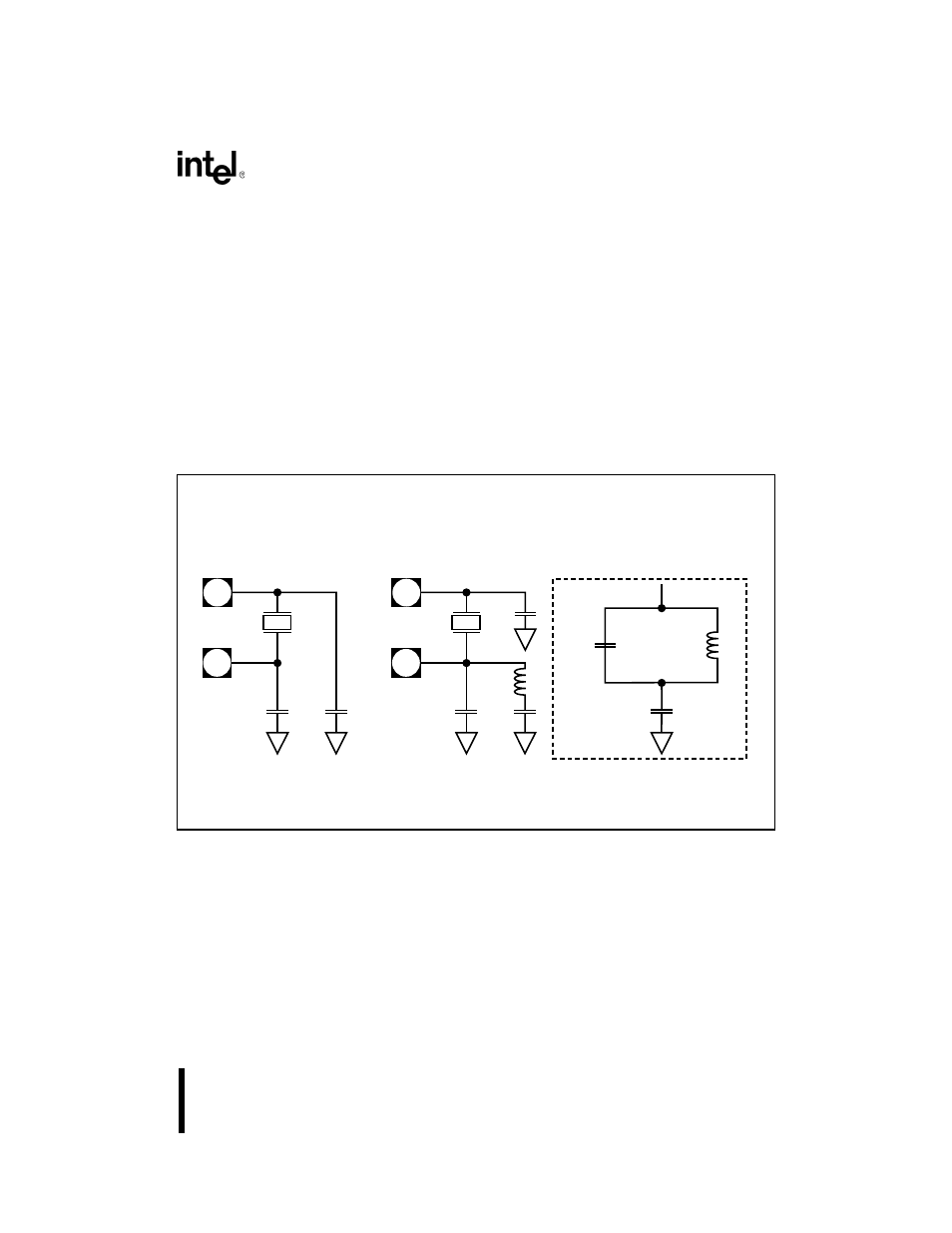
Choose C
1
and L
1
component values in the third overtone crystal circuit to satisfy the following
conditions:
•
The LC components form an equivalent series resonant circuit at a frequency below the
fundamental frequency. This criterion makes the circuit inductive at the fundamental
frequency. The inductive circuit cannot make the 90° phase shift and oscillations do not
take place.
•
The LC components form an equivalent parallel resonant circuit at a frequency about
halfway between the fundamental frequency and the third overtone frequency. This
criterion makes the circuit capacitive at the third overtone frequency, necessary for oscil-
lation.
•
The two capacitors and inductor at X2, plus some stray capacitance, approximately equal
the 20 pF load capacitor, C
X2
, used alone in the fundamental mode circuit.
Figure 5-3. Crystal Connections to Microprocessor
Choosing C
1
as 200 pF (at least 10 times the value of the load capacitor) simplifies the circuit
analysis. At the series resonance, the capacitance connected to L
1
is 200 pF in series with 20 pF.
The equivalent capacitance is still about 20 pF and the equation in Figure 5-4(a) yields the series
resonant frequency.
X1
X2
(a)
Fundamental
Mode Circuit
X1
X2
(b)
Third Overtone
Mode Circuit
C
X2
C
X1
C
X2
C
X1
L
1
(c)
Third Overtone Mode
(Equivalent Circuit)
C
X2
L
1
C1
C
X1
= C
X2
C
1
L
1
= 20pF
= 200pF
= (See text)
A1520-0A