Figure 41. pcb relocation register, Cation register (figure 4-1 – Intel 80C188XL User Manual
Page 131
PERIPHERAL CONTROL BLOCK
4-2
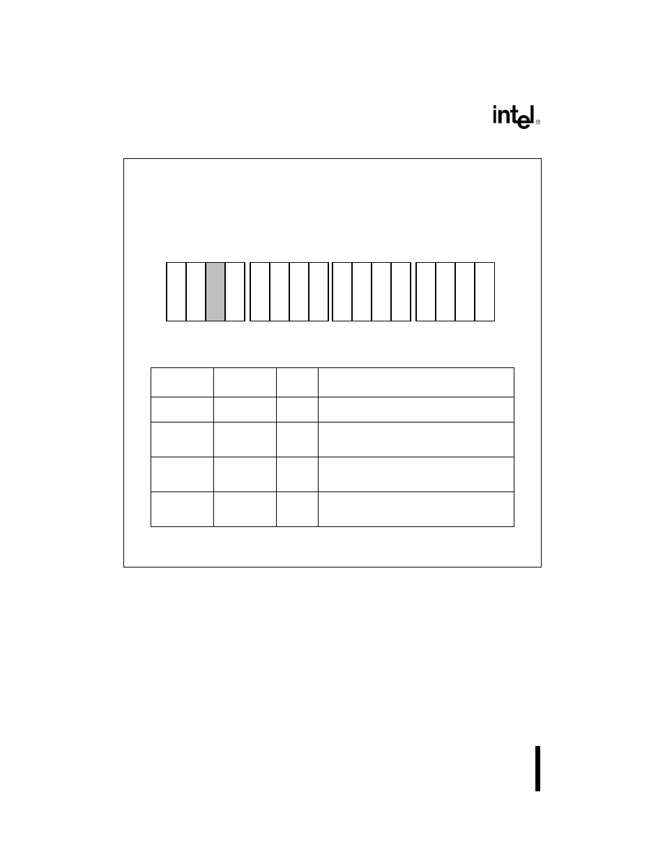
Figure 4-1. PCB Relocation Register
Register Name:
PCB Relocation Register
Register Mnemonic:
RELREG
Register Function:
Relocates the PCB within memory or I/O space.
Bit
Mnemonic
Bit Name
Reset
State
Function
ET
Escape Trap
0
If ET is set, the CPU will trap when an ESC
instruction is executed.
SL
Slave/Master
0
If SL is set, the Interrupt Control Unit operates in
slave mode. If SL is clear, it operates in master
mode.
MEM
Memory I/O
0
If MEM is set, the PCB is located in memory
space. If MEM is clear, the PCB is located in I/O
space.
R19:8
PCB Base
Address
Upper Bits
0FFH
R19:8 define the upper address bits of the PCB
base address. All lower bits are zero. R19:16 are
ignored when the PCB is mapped to I/O space.
NOTE:
Reserved register bits are shown with gray shading. Reserved bits must be written
to a logic zero to ensure compatibility with future Intel products.
15
0
M
E
M
R
1
9
R
1
8
R
1
7
R
1
6
R
1
5
R
1
4
R
1
0
R
9
R
8
R
1
1
E
T
R
1
2
R
1
3
S
L
A1262-0A