Middleby Marshall RED LOBSTER PS200-R68 User Manual
Page 86
80
SECTION 7
ELECTRICAL SCHEMATICS
orn
#
1
6
#
1
6
1
R
C1
2
3
5
4
6
13
14
n
e
u
tr
a
l
-M
AC SP
9
10
C1
o
rn
+M AC
-M
AC SP
+M AC
#16
1
2
3
4
5
6
G
neutral # 16
#16
#16
#16
3
4
4
3
A1
A2
9A
9A
9A
XFMR
24V
115V
4
3
C
om
C
ount
+5V
C
om
C
ount
+5V
wht
Contactor Coil
b
lk
re
d
w
h
t
b
rn
b
lk
l
in
e
-1
re
d
l
in
e
-2
w
h
t
Door Interlock
Switch
blk
Motor
blk
w
h
t
wht
Blower Switch
Heat
Switch
Cooldown(TC)
N.O. 180˚F(82˚C)
Hi-Limit
(TC)
N.O. 650˚F (343˚C)
brn
yel
blk
wht
red
b
lk
re
d
yel
Centrifugal
Switch
wht
brn
wht
Relay Coil
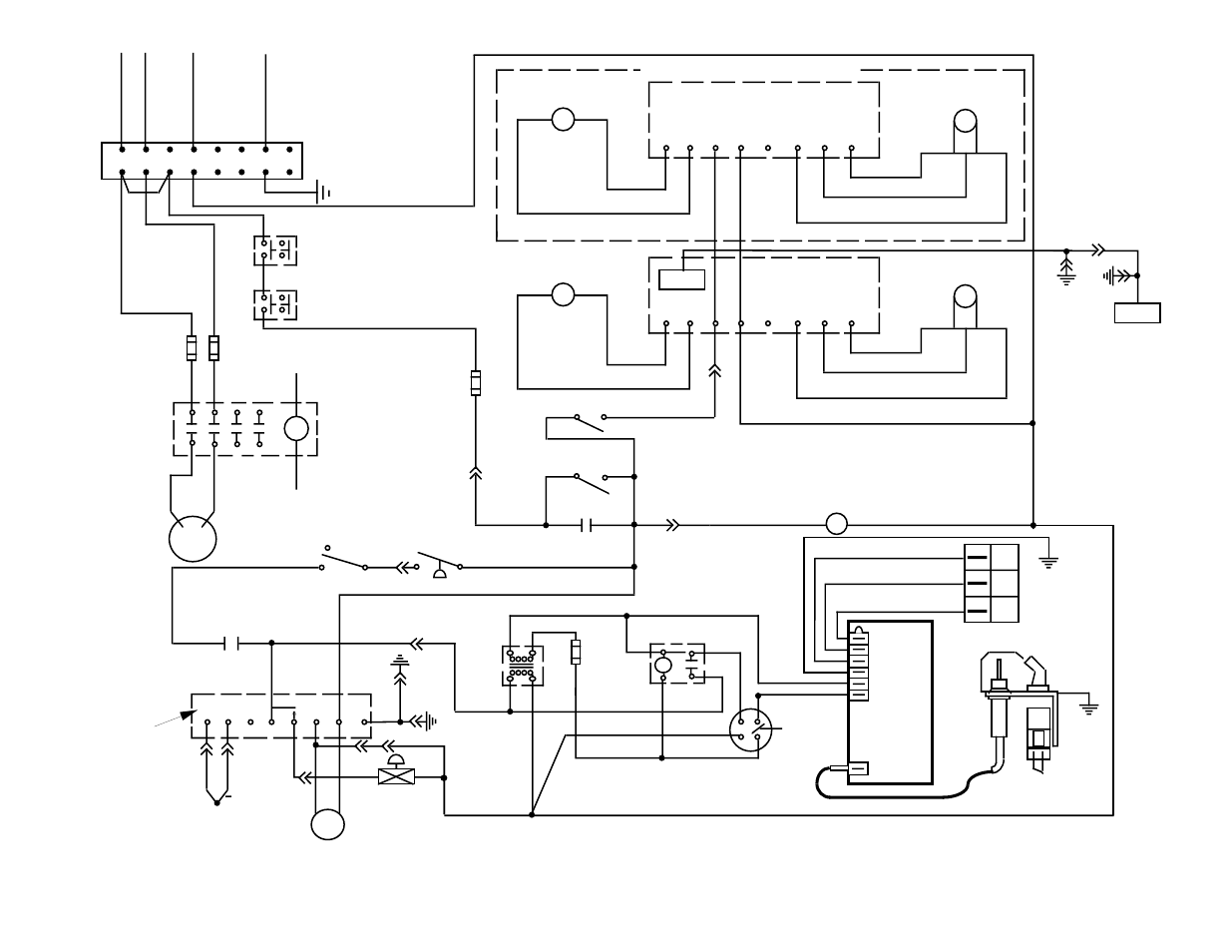
SERIES PS200-R68 GAS OVEN SCHEMATIC
208-240V Main Blower Motors, 50/60Hz, 120V Control Circuit, 1 Ph,
4.1 Amp Draw, 3 Pole, 4 Wire (2 hot, 1 neut, 1 grd)
D.C. Motor
Pick-up
blk
w
h
t
w
h
t
grn
b
lk
w
h
t
For use in split belt applications only
b
lk
Rear Interlock
Switch
Air
Pressure
Switch
N.O.
b
lk
b
lk
L
IN
E
-1
L
IN
E
-2
Terminal
Block
Gnd
blk
blk
yel
b
rn
y
e
l
Conveyor Switch
yel
D.C. Control
D.C. Motor
D.C. Control
Pick-up
w
h
t
grn
b
lk
11
12
purple
p
u
rp
le
yel
24V Gnd
MV
MV/PV
PV
wht
red
blu
g
rn
Valve
Terminals
Pilot
Burner
Ignitor
Sensor
To Gas Control
Pilot Outlet
Pilot
Burner
Gnd
Ignition
Module
Spark
24V
Gnd
PV
PV
MV
MV
8
7
6
5
L2 L1 Gnd
+
T/C
4
wht
wht
High Flame
Solenoid Valve
Temperature
Controller
(TC)
w
h
t
re
d
grn
b
lu
J1-1
J
1
-3
J2-22
J2-23
J1-2
J1-14
J1-5
J1-13
Fan
J2
pins 1-12
J2-24
J
2
-2
4
Thumbwheel
with 12
conductor
ribbon cable
J1-6
b
lk
b
lk
J1-4
Burner Blower
Motor
grn
J1-16
J1-15
g
rn
g
rd