Caution, Warning, Middleby marshall – Middleby Marshall RED LOBSTER PS200-R68 User Manual
Page 25: Canadian gas association
19
SECTION 2
INSTALLATION
VI. ELECTRIC SUPPLY FOR GAS HEATED OVENS
Electric supply for all gas heated ovens is 208-240 volts
AC single phase. Each oven requires a separate 15 amp
service. Connection is made as shown in Figures 2-8 &
2-12. A separate ground wire must also be supplied.
CAUTION: Before connecting incoming power to oven,
a voltage reading of each leg to neutral must be made.
These readings should not normally exceed 120 volts
each.
If one of the incoming legs reads over 130 volts, this
indicates the supply voltage has a high leg.
Export ovens are supplied with a stepdown transformer
for the 110V control circuit.
Call your local electrician or electrical power supply
company and have them remove the high leg from the
electrical supply line for the oven.
Connecting a high leg to the black lead of the oven will
severely damage many of the electrical components in
the oven.
CONNECTING A HIGH LEG TO THE BLACK WIRE
VOIDS ALL OVEN WARRANTIES.
NOTE:
When the oven is installed it must be electrically
grounded in accordance with local codes, or in the
absence of local codes. ANSI/NFPA - Latest edition.
CAUTION
IT IS REQUIRED THAT THE OVEN BE
PLACED UNDER A VENTILATION HOOD
FOR ADEQUATE AIR SUPPLY
AND VENTILATION
WARNING
OVEN MUST BE KEPT CLEAR
OF COMBUSTIBLES
AT ALL TIMES.
CAUTION:
The power burner will not operate and gas will not flow through the burner
without electric power. No attempt should be made to operate the oven during
power failure.This oven is to be operated only on the type of gas as shown on
the specification data plate.
A MIDDLEBY COMPANY
Middleby
Marshall
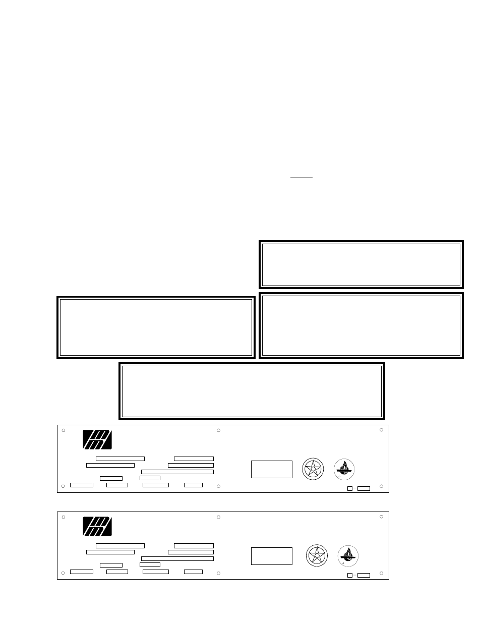
MODEL NO.
ID NO.
INPUT BTU PER HOUR MAXIMUM
MAN. PRESS.
"INTENDED FOR OTHER THAN HOUSEHOLD USE"
FOR INSTALLATION UNDER VENTILATING HOOD ONLY
SUITABLE FOR INSTALLATION ON COMBUSTIBLE FLOORS ADJACENT
TO COMBUSTIBLE AND NONCOMBUSTIBLE WALLS WITH THE FOLLOW-
ING MINIMUM CLEARANCES: ZERO INCHES TO RIGHT SIDE WALL,
EIGHTEEN INCHES TO LEFT SIDE WALL, SIX INCHES TO BACK WALL.
SERIAL NO.
TYPE OF GAS
IN.W.C.
WIRE WITH GROUND
VAC
AMPS
AMPS
HZ
MANUFACTURED UNDER U.S. PATENT NUMBERS 3,844,213 AND 4,154,861
ELGIN, ILLINOIS, 60120, U.S.A. COMMERCIAL OVEN ANS Z 83.12
ACCEPTED FOR USE
CITY OF NEW YORK
DEPARTMENT OF BUILDINGS
MEA 309-83-E
DATA PLATE FOR OVENS WITH THE MACHINERY/DRIVE COMPARTMENT LOCATED AT THE LEFT END OF OVEN
A MIDDLEBY COMPANY
Middleby
Marshall
MODEL NO.
ID NO.
INPUT BTU PER HOUR MAXIMUM
MAN. PRESS.
"INTENDED FOR OTHER THAN HOUSEHOLD USE"
FOR INSTALLATION UNDER VENTILATING HOOD ONLY
SUITABLE FOR INSTALLATION ON COMBUSTIBLE FLOORS ADJACENT
TO COMBUSTIBLE AND NONCOMBUSTIBLE WALLS WITH THE FOLLOW-
ING MINIMUM CLEARANCES: ZERO INCHES TO LEFT SIDE WALL,
EIGHTEEN INCHES TO RIGHT SIDE WALL, SIX INCHES TO BACK WALL.
SERIAL NO.
TYPE OF GAS
IN.W.C.
WIRE WITH GROUND
VAC
AMPS
AMPS
HZ
MANUFACTURED UNDER U.S. PATENT NUMBERS 3,844,213 AND 4,154,861
ELGIN, ILLINOIS, 60120, U.S.A. COMMERCIAL OVEN ANS Z 83.12
ACCEPTED FOR USE
CITY OF NEW YORK
DEPARTMENT OF BUILDINGS
MEA 309-83-E
DATA PLATE FOR OVENS WITH THE MACHINERY/DRIVE COMPARTMENT LOCATED AT THE RIGHT END OF OVEN
DE SIGN
C ERT
IFIE
D
A
M E
RIC A
N
G S
A
A
S
S
O C
IA
T I
O
N
CANADIAN GAS ASSOCIATION
APPROVED
R
DE SIGN
C ERT
IFIE
D
A
M E
RIC A
N
G S
A
A
S
S
O C
IA
T I
O
N
CANADIAN GAS ASSOCIATION
APPROVED
R
Figure 2-11.
Oven Specifi-
cation Data
Plate Refer-
ence
Connect one 208-240V supply leg to the black wire and
the other 208-240V supply leg to the red wire. The supply
neutral should connect to the white oven wire and supply
ground should connect to the oven ground screw located
in the main junction box.
VII. ELECTRICAL CONNECTION
INFORMATION FOR ALL OVENS.
Check the oven data plate before making any electrical
connections. Connections must agree with data on oven
data plate (Refer below to Figure 2-11).
NOTE: In Canada with C22.1,Part 1 and/or local code.
A fused disconnect switch or circuit breaker (not fur-
nished) MUST be installed in the electrical supply line
FOR EACH OVEN. A lockout/tagout electrical shutoff
must be installed for each oven, refer to Figure 2-9. The
service connection must meet all national and local
electrical code requirements. All connections are made
at one common connection at the back of each control
box.