Indicators, switches, and interfaces, Indicators, switches, and interfaces -13, Front view of the ultranet edge 3000 -13 – McDATA ULTRANETTM EDGE STORAGE ROUTER 3000 User Manual
Page 53: Front panel switches, controls, and interfaces -13
2
Hardware Configurations
2-13
Indicators, Switches, and Interfaces
Indicators, Switches, and Interfaces
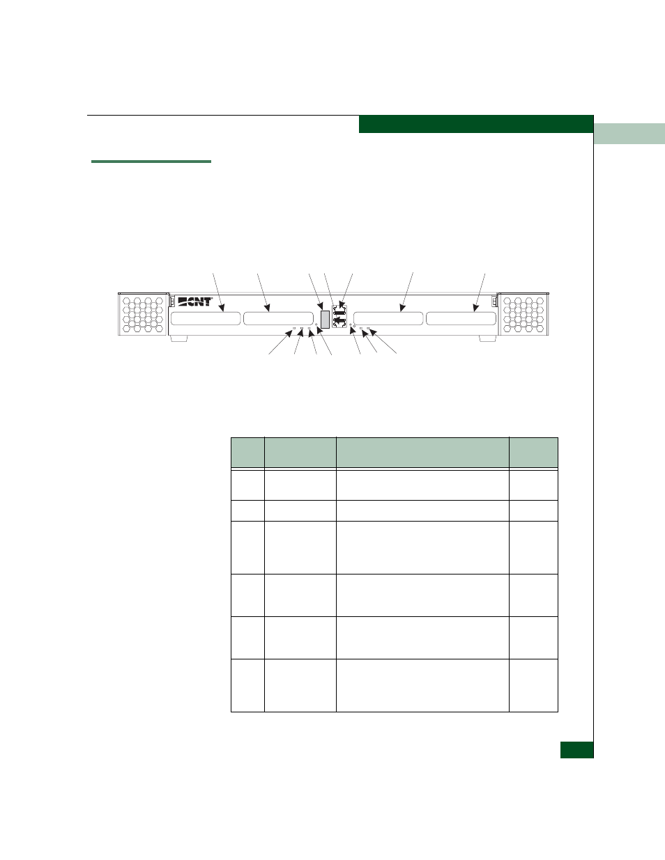
Located on the front of the UltraNet Edge 3000 are the four physical
I/Os, the Ethernet RJ-45 (maintenance interface), the alphanumeric
messages window, and the LEDs (See Figure 2-4). These components
are described in Table 2-9.
Figure 2-4
Front View of the UltraNet Edge 3000
Sb010
I/O-3
I/O-4
I/O-2
I/O-1
1
8
10
14
2
11
9
7
6
5
4
3
13
12
Table 2-9
Front Panel Switches, Controls, and Interfaces
Index
Type
Function
Normal
Operation
1
I/O-1
This slot is available for a Fibre Channel card,
or Gigabit Ethernet card (3x1 configurations).
2
I/O-2
This slot is available for a Fibre Channel card.
3
I/O-0
(Ethernet
Maintenance
Interface)
One 10/100 BASE-T Ethernet RJ-45
maintenance interface used for maintenance,
diagnostics, and network monitoring via a
Telnet or FTP session.
4
Serial interface
connector
One RS-232 RJ-45 interface which runs at
38.4 Kbaud, 8N1 used for maintenance and
diagnostic connections.
5
Alphanumeric
messages
window
Used for displaying the node number. It can
also be used for diagnostic debug.
6
I/O-3
This slot is available for a 10/100 Ethernet,
Gigabit Ethernet, OC-3 ATM, or Fibre Channel
card. See Table 2-6 for valid hardware
configurations.