McDATA ULTRANETTM EDGE STORAGE ROUTER 3000 User Manual
Page 357
B-11
Initial Power-On Procedure
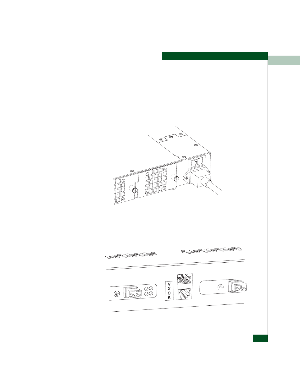
5. Turn the power switch(es) to the On (
⏐
) position (this activates the
systems initial loading routine). The power switch is located
directly above the power cord, see Figure B-4.
Verify status with the indicator lights and the Alphanumeric
messages
window display on front of the unit. (See the “Indicators,
Switches, and Interfaces” section in Chapter 2 for descriptions of the
indicators and alphanumeric displays or the “LED Diagnostic Codes”
section in Chapter 13, Troubleshooting and Diagnostics).
Figure B-4
Power Supply Switch
After power up, the diagnostic display will toggle between VXOK
and BOTP. The UltraNet Edge 3000 is then ready for the UltraNet
ConfigManager configuration.
Figure B-5
Diagnostic Display
Sb035
I
Sb108