Layer 3 switch, Overview, Ip directed broadcasts – Motorola 2.1 User Manual
Page 23: Layer 3 switch -9, Overview -9, Ip directed broadcasts -9, Figure 2-3, Cisco 3750 l3 -9, Ip address host
Chapter 2: Network Setup
IP Address
Host
DHCP Pool 10.49.0.30 – 10.49.255.254
VLAN 49 (802.11 clients)
VLAN 49 Address Pool
Layer 3 Switch
Overview
The standard small system reference design includes a Cisco 3750 L3 Switch which supports
20 Intelligent Access Points (IAPs). Four switch ports (ports 1-4) are also available for
network servers such as the One Point Wireless Manager™ server and RADIUS. IAPs are
connected to L3 switch (ports 5-24) via one of three methods:
•
Direct Ethernet
•
Connection via a wireless bridge (Motorola Canopy™ System)
•
Connection via a wireline media converter (e.g. Ethernet over Fiber media
converter)
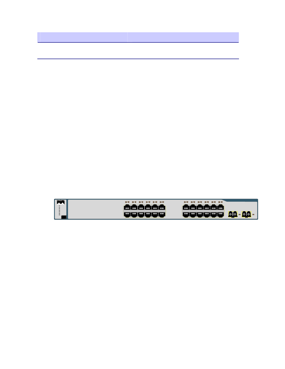
Figure 2-3
Cisco 3750 L3
MODE
STACK
SPEED
DUPLX
STAT
MASTR
RPS
SYST
1
2
3
4
5
6
7
8
9 10
11 12
1X
2X
11X
12X
13 14
15 16
17 18
19 20
21 22
23 24
13X
14X
23X
24X
Catalyst 3750
SERIES
1
2
The Cisco 3750 router provides the following services:
•
Routing between the wireless subnets 10.1.0.0 /16, 10.24.0.0/16, 10.49.0.0/16,
and the server network 172.31.0.0/16 (e.g. inter VLAN routing between VLANs
1, 24, 31, and 49).
•
DHCP relay from the wireless subnets to the DHCP server running on the One
Point Wireless server 172.31.0.20.
•
802.1Q VLAN tag recognition enabling the support of a trunked set of VLANs
terminating on a single physical interface
IP Directed Broadcasts
By default, the 3750 Switch drops IP directed broadcasts; thus preventing them from being
forwarded. The One Point Wireless Manager™ application utilizes SNMP broadcasts for
automatic network discovery. We have enabled IP directed broadcasts in the 3750 L3 switch
2-9