Part ii – power cable with flying leads, Part ii – power cable with flying leads -23, Figure 9-28 – Motorola 2.1 User Manual
Page 124: Power cable with wire designation -23, Figure 9-29
Appendix A:
Part II – Power Cable with Flying Leads
1.
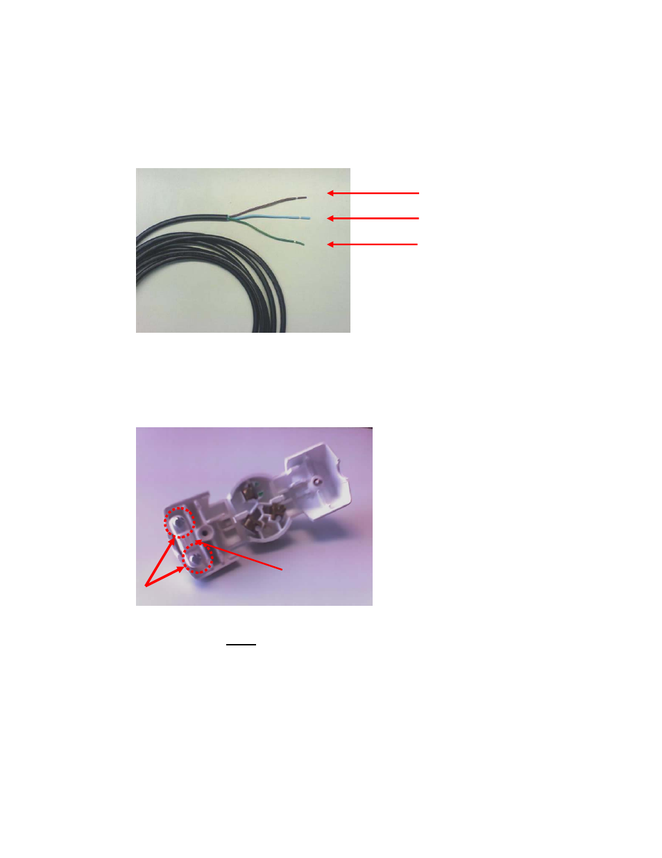
The initial Power Cable will have three wires: Brown (Line), Blue (Neutral), and Green/Yellow
(Ground/Earth).
Figure 9-28
Power Cable with Wire Designation
Brown Wire is Line
Blue Wire is Neutral
GREEN/Yellow Wire is Earth
Part III – Power Connector and Cable Assembly Instructions
2.
Loosen the Strain Relief Screws on the plug.
Figure 9-29
Inside View Pointing out Strain Relief Bar and Screws
Strain Relief Screws
Strain Relief Bar
3.
Place the three wires under the Strain Relief Bar and pull through. Allow the Blue and Green
Wire
to pull through on the left side of the Screw Well and the Brown Wire to pull through on the
right hand side of the Screw Well.
9-23
See also other documents in the category Motorola Hardware:
- SB5101U DOCSIS 2.0 Cable Modem (16 pages)
- PTP 500 (20 pages)
- Netopia 3347-02-ENT (3 pages)
- SBV5220 (64 pages)
- AP-51XX (698 pages)
- SURFboard SVG2501 Series (34 pages)
- MESH Wireless Router MWR6300 (2 pages)
- MVME712AM (74 pages)
- SURFBOARD SBG1000 (16 pages)
- RSGu3502 (5 pages)
- SURFboard SBG941U (78 pages)
- Netopia 2240N-VGx (5 pages)
- SURFboard SVG2501 (8 pages)
- WR850G (93 pages)
- WR850GP (95 pages)
- USBW 200 (12 pages)
- ONCE SC140 (28 pages)
- Netopia 3300 (368 pages)
- MPC8260 (1006 pages)
- WNS25 (2 pages)
- Netopia 7000 (254 pages)
- Viadux 2000 Subscriber Bridge RC2010 (1 page)
- MVME5100 Series (5 pages)
- ColdFire MCF5282 (766 pages)
- MC9S12C-Family (136 pages)
- CG4500 (36 pages)
- SBG900 (130 pages)
- SURFBOARD SB5100 (2 pages)
- SURFboard SB6180 (20 pages)
- SURFBOARD SBG900 (16 pages)
- SURFboard SVG1501U (83 pages)
- SB5100 (74 pages)
- T3 (2 pages)
- H375 (5 pages)
- NETOPIA 2247/57-62 (22 pages)
- SBV5120 (56 pages)
- SBV5120 (57 pages)
- RG2200 (88 pages)
- CME-12B/BC (18 pages)
- SURFboard 574823-001-a (2 pages)
- SURFboard Cable Modem (66 pages)
- CME-12D60 (19 pages)
- DIGITAL VOICE MODEM SBV5122 (24 pages)
- SB4000 (2 pages)
- Canopy FSK and OFDM radios PTP 200 (OFDM (56 pages)