Conveyor belt replacement – Grizzly G0486/G0487 User Manual
Page 36
-34-
G0486/G0487 Wide Belt Sander
7. Insert two 2x4 x 8' wooden studs under the
table to support the table, and then (with
help) lift the table slightly and move it out of
the rear of the machine.
8. Disconnect the limit switch, remove all mount-
ing screws, and remove the emergency stop
push-panel assembly.
9. Turn both tracking adjustment bolts coun-
ter-clockwise five turns, remove one roller
support, and slide the drum out of the table
assembly.
10. Remove the old conveyor belt, inspect roll-
ers, bearings, and table for wear and replace
as required.
11. Install the new conveyor belt. Note: The belt
is non-directional.
12. Install the front roller, the roller support, and
turn both tracking adjustment bolts clock-
wise equally so the conveyor belt becomes
taught and does not hang loose. DO NOT
OVERTIGHTEN the belt.
13. With a helper, install the table from the rear
in a similar fashion as it was removed.
14. Install the table guides and the left and right
lower access panels.
15. Align the lead screw flanges with the marks
made in
Step 6, and install the hex bolts.
16. Install the table height limit switches so the
upper switch clicks when the conveyor sur-
face is
1
⁄
4
" away from the sandpaper, and the
lower switch clicks when the conveyor table
is
1
⁄
4
" higher than its lowest position. Make
sure that you manually test your settings with
the hand wheel so you don't crash the table
if incorrectly set.
17. With a helper, install the gearbox, vibration
dampener washers, and mounting bracket.
18. Install the emergency stop push panel assem-
bly and the limit switch.
19. Start the conveyor motor and turn the con-
veyor tracking bolts as required until the
conveyor belt tracks straight without loading
up on one side of the table.
Conveyor Belt
Replacement
Tools Needed:
Qty
Make sure that you have a lifting device or anoth-
er person to help in table removal.
9 mm Hex Wrench ............................................. 1
19 mm Combination Wrench ............................. 1
12 mm Combination Wrench ............................. 1
14 mm Combination Wrench ............................. 1
#2 Phillips Screwdriver ..................................... 1
8' 2x4s
.............................................................. 2
Permanent Marker
............................................ 1
To remove the conveyor belt, use Figure 38
and match the number with the steps below:
1. Raise the table up so the conveyor belt
is approximately two-inches away from
the sanding roller or platen, and then
DISCONNECT THE SANDER FROM THE
POWER SOURCE!
2. Remove the gearbox mounting bracket, and
with an assistant's help, slide the motor and
gearbox from the roller shaft and lower it to
the floor.
Note: Do not loosen the two vibration damp-
ener washers shown in
Figure 38.
3. Remove two table height limit switches.
4. Remove both lower access panels.
5. Remove the left and right table guides.
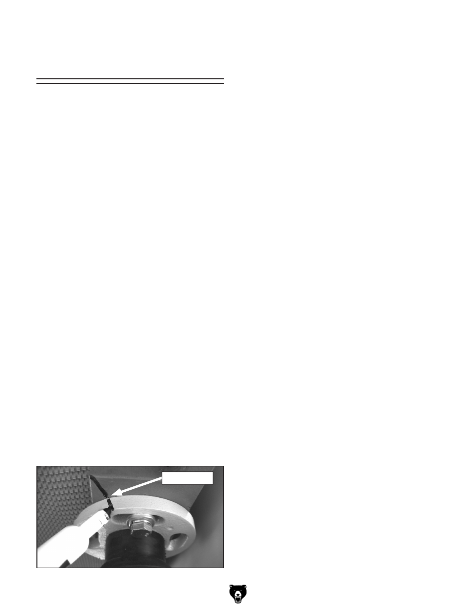
6. Using a permanent marker, mark all four
lead screw flange positions (
Figure 37), and
remove all hex bolts from the flanges.
Figure 37. Marking lead screw for reassembly.
Timing Mark