FUJITSU MHR2030AT User Manual
Page 98
Interface
5-24
C141-E145-02EN
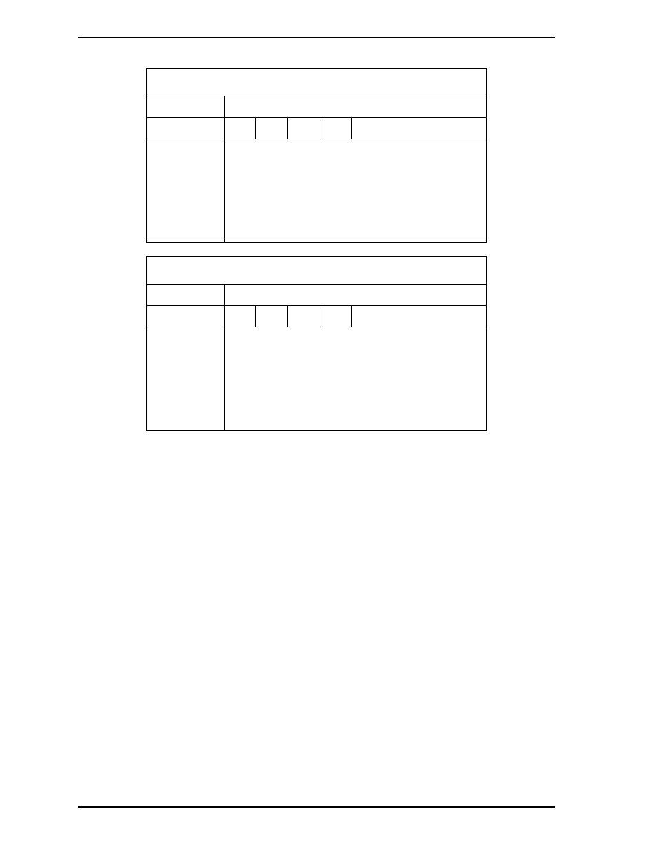
At command issuance (I/O registers setting contents)
1F7
H
(CM)
0
1
0
0
0
0
0
R
1F6
H
(DH)
x
L
x
DV
Start head No. / LBA [MSB]
1F5
H
(CH)
1F4
H
(CL)
1F3
H
(SN)
1F2
H
(SC)
1F1
H
(FR)
Start cylinder No. [MSB] / LBA
Start cylinder No. [LSB] / LBA
Start sector No. / LBA [LSB]
Transfer sector count
xx
At command completion (I/O registers contents to be read)
1F7
H
(ST)
Status information
1F6
H
(DH)
x
L
x
DV
End head No. / LBA [MSB]
1F5
H
(CH)
1F4
H
(CL)
1F3
H
(SN)
1F2
H
(SC)
1F1
H
(ER)
End cylinder No. [MSB] / LBA
End cylinder No. [LSB] / LBA
End sector No. / LBA [LSB]
00 (*1)
Error information
*1
If the command is terminated due to an error, the remaining number of
sectors of which data was not transferred is set in this register.
(5) WRITE SECTOR(S) (X’30’ or X’31’)
This command writes data of sectors from the address specified in the
Device/Head, Cylinder High, Cylinder Low, and Sector Number registers to the
address specified in the Sector Count register. Number of sectors can be specified
from 1 to 256 sectors. A sector count of 0 requests 256 sectors. Data transfer
begins at the sector specified in the Sector Number register. For the DRQ,
INTRQ, and BSY protocols related to data transfer, see Subsection 5.4.2.
If the head is not on the track specified by the host, the device performs an
implied seek. After the head reaches to the specified track, the device writes the
target sector.
If an error occurs when writing to the target sector, retries are attempted
irrespectively of the R bit setting.
The data stored in the buffer, and CRC code and ECC bytes are written to the data
field of the corresponding sector(s). Upon the completion of the command
execution, the command block registers contain the cylinder, head, and sector
addresses of the last sector written.