4 settings for connection or navigator, E123, 4 settings for connection of navigator – Furuno GPS NAVIGATOR GP-150 User Manual
Page 54
8. MENU SETTINGS
8-6
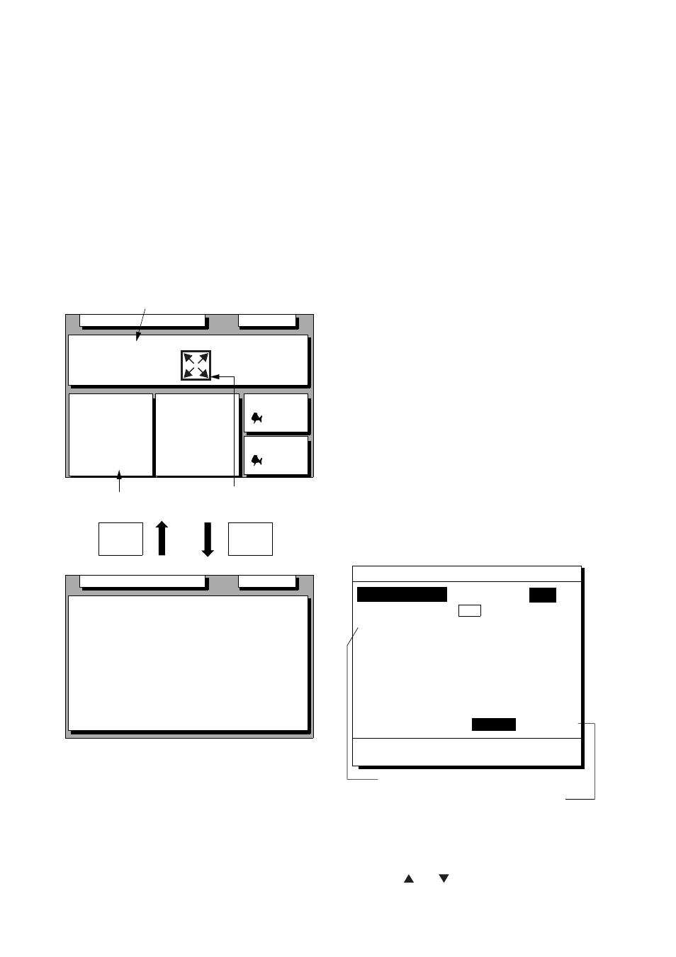
Enlarging characters
The size of the indications of position or user
defined display areas can be enlarged on the
Data display.
1) On the Data display, with no enlarged
characters, press the CURSOR ON/OFF
key to turn on the zoom icon.
2) Operate the cursor keys to select data to
enlarge in the window.
3) Press the ZOOM IN key.
To switch character size from enlarged to
normal, press the ZOOM OUT key at step 3.
SEP 12, 2009 23:59'59" U
N12
˚
E123
˚
Position
23.456'
23.456'
SEP 12, 2009 23:59'59" U
12˚ 23.456' N
123˚ 23.456' E
Position
RNG
31.23
NM
SOG
12.3
kn
BRG
223.4˚
COG
123.4˚
TO : 001
MARINE
POINT1
NEXT
: 002
MARINE
POINT2
ZOOM
IN
ZOOM
OUT
Position
User-defined
display window
W84
W84
D3D
100m
* SAFE
D3D
100m
* SAFE
Zoom icon
Figure 8-7 How to enlarge indications on the
data display
8.4 Settings for Connection
of Navigator
Besides its fundamental function of
displaying position, the GP-150 can also
output various data to external equipment.
Before outputting data to external equipment,
first determine what data the external
equipment requires. Output only necessary
data to ensure data will be output correctly.
All data transmitted by marine electronics
equipment are prefixed with a two character
code called a talker. The same talker must
be shared by the transmitting and receiving
equipment to transmit and receive data
successfully. The GP-150 transmits data
using the GP (GPS talker), however it can
also transmit using the Loran (LC) or Decca
(DE) talker.
Because the GP talker is a relatively new
system some early model equipment may
not recognize this talker.
DATA 1 output setting
1) Press MENU ESC, 9 and 3. The DATA 1,
3 OUTPUT SETUP menu appears.
Talker ID GP LC DE
Output Data (00-90 sec)98%
1. AAM:00 APA:00 APB:04 BOD:00
2. BWR:00 BWW:00 GGA:00 GLL:01
3. RMB:01 RMC:00 VTG:01 WCV:00
4. VDR:00 WPL:00 XTE:00 ZDA:01
5. GNS:00 GBS:01 Rnn:00 RTE:00
DATA3. Log Pulse 400ppm
DATA 1, 3 OUTPUT SETUP
MENU : Escape
ENT : Enter
Settings shown here are default settings.
This line appears only when LOG is
selected by internal jumper wires.
Data FMT
V1.5 V2.0
IEC
200ppm
Figure 8-8 DATA 1, 3 OUTPUT
SETUP menu
2) Press or to select Data Fmt.