8 reset button connector, 9 sata drive connectors – IEI Integration ECW-281B-N270-WT v2.10 User Manual
Page 44
ECW-281B-R21/N270 Embedded System
Page 28
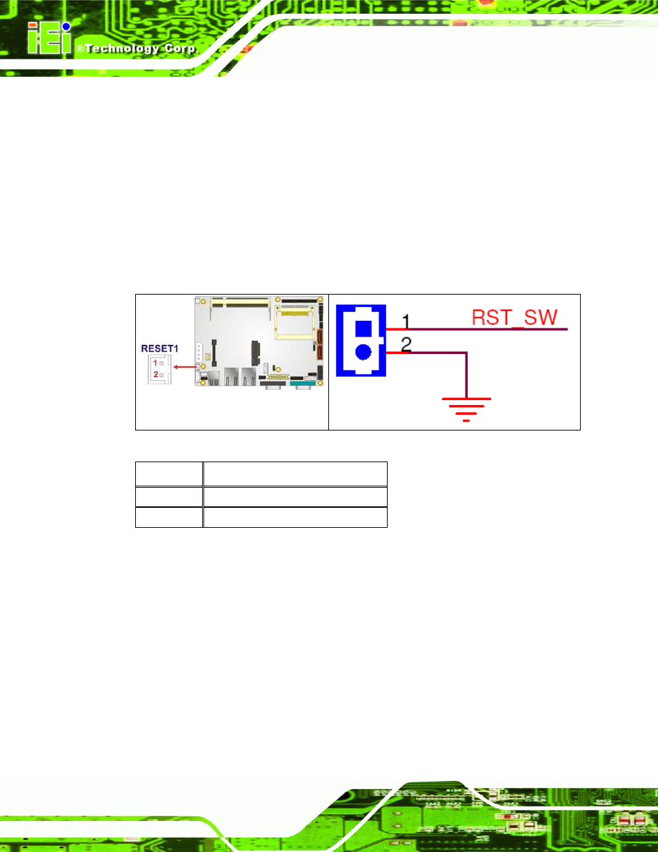
3.3.8 Reset Button Connector
CN Label:
RESET1
CN Type:
2-pin wafer (1x2)
CN Location:
See
713H713H715H
Figure 3-9
CN Pinouts:
See
714H714H716H
Table 3-9
The reset button connector is connected to a reset switch on the system chassis to enable
users to reboot the system when the system is turned on.
Figure 3-9: Reset Button Connector Locations
PIN NO.
DESCRIPTION
1 Reset
Switch
2 GND
Table 3-9: Reset Button Connector Pinouts
3.3.9 SATA Drive Connectors
CN Label:
SATA1
, SATA2
CN Type:
7-pin SATA drive connectors
CN Location:
See
793H715H715H717H
Figure 3-10
CN Pinouts:
See
794H716H716H718H
Table 3-10
This manual is related to the following products: