D1.3 ipm-ata-cf, Figure d1.3 ipm-ata-cf board layout, Table d1.3 ipm-ata-cf jumper description – Inova PD00941013.001 User Manual
Page 89: Compactpci, Ipm-ata, Appendix d
©2004 Inova Computers GmbH
Page D-5
ICP-P4/PM/CM Appendix-D
Appendix D
IPM-ATA
CompactPCI
®
D
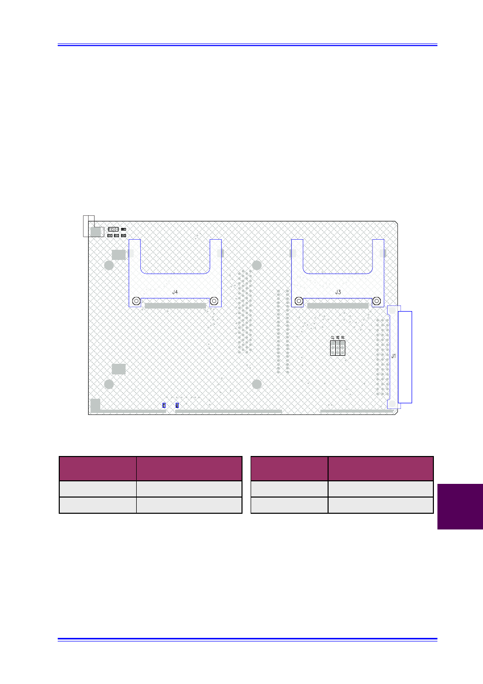
D1.3 IPM-ATA-CF
The IPM-ATA-CF has provision for one or two standard Compact FLASH or MicroDrive devices.
Figure D1.3 illustrates the significant connectors for this device while Table D1.3 indicates the
jumper settings for the various Master/Slave device configurations.
Figure D1.3 IPM-ATA-CF Board Layout
1
2
3
Table D1.3 IPM-ATA-CF Jumper Description
It should be noted that the secondary IDE channel only (from rear I/O) is available for use by the
IPM-ATA-CF (the primary is on the CPU board itself). Multi Master or multi Slave configurations
are not supported and will not work!
Jumper J6
Jumper J7
2-3
2-3
Open
Open
CompactFlash
or MicroDrive in J4
Master
Slave
Master
Slave
CompactFlash
or MicroDrive in J3