C1.8 fast ethernet interface, Figure c1.8 fast ethernet interface pinout, Table c1.8 fast ethernet connector signals – Inova PD00941013.001 User Manual
Page 80: Itm-rio, Appendix c
©2004 Inova Computers GmbH
Page C-10
ICP-P4/PM/CM Appendix-C
ITM-RIO
Appendix C
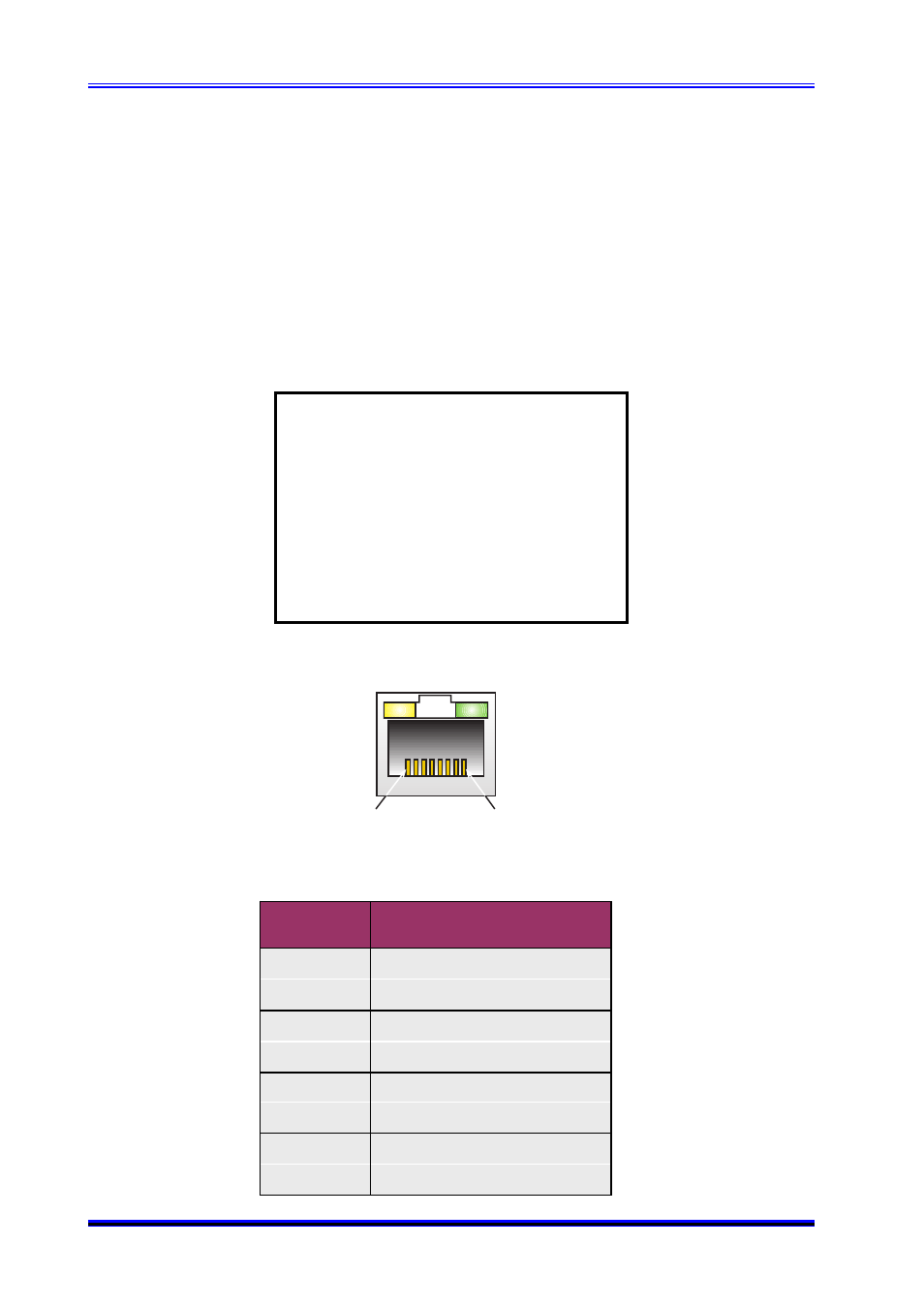
C1.8 Fast Ethernet Interface
Standard to all rear I/O (D) transition modules is the Fast Ethernet connection. Figure C1.8 and
Table C1.8 provide the pinout and signal description of this standard Ethernet interface respec-
tively. Although the LEDs feature on the Ethernet connector, these are not physically connected to
the rear I/O interface board. Instead, if this interface is used, communication traffic can still be
observed on the front-panel Ethernet connector!
Note:
The single channel Fast Ethernet
option in table C1.10 is either ETH 1
or ETH 2 on the front-panel depending
on the computer platform. If the rear
I/O option is used then the front-panel
connection using the same controller
must not be used. Doing so will
disrupt the communication leading to
spurious results.
Figure C1.8 Fast Ethernet Interface Pinout
8
1
Table C1.8 Fast Ethernet Connector Signals
Pin No.
Signal Description
Ethernet / Fast Ethernet
1
TX0+
2
TX0-
3
RX0+
4
5
6
RX0-
7
8