A2 icp-hd-3(-nd) interfaces, A2.1 com1 & com2 interfaces, Figure a2.1 com1 & com2 interface pinout – Inova PD00941013.001 User Manual
Page 63: Table a2.1 com1 & com2 connector signals, A2 icp-hd-3(-nd) interfaces ......... a-5, Compactpci, Icp-hd-3, Appendix a
©2004 Inova Computers GmbH
Page A-5
ICP-PM/CM Appendix-A
Appendix A
ICP-HD-3
CompactPCI
®
A
A2 ICP-HD-3(-ND) Interfaces
The carrier board serves not just to mount an IDE mass-storage device - it also provides the user
with a wealth of familiar standard PC interfaces.
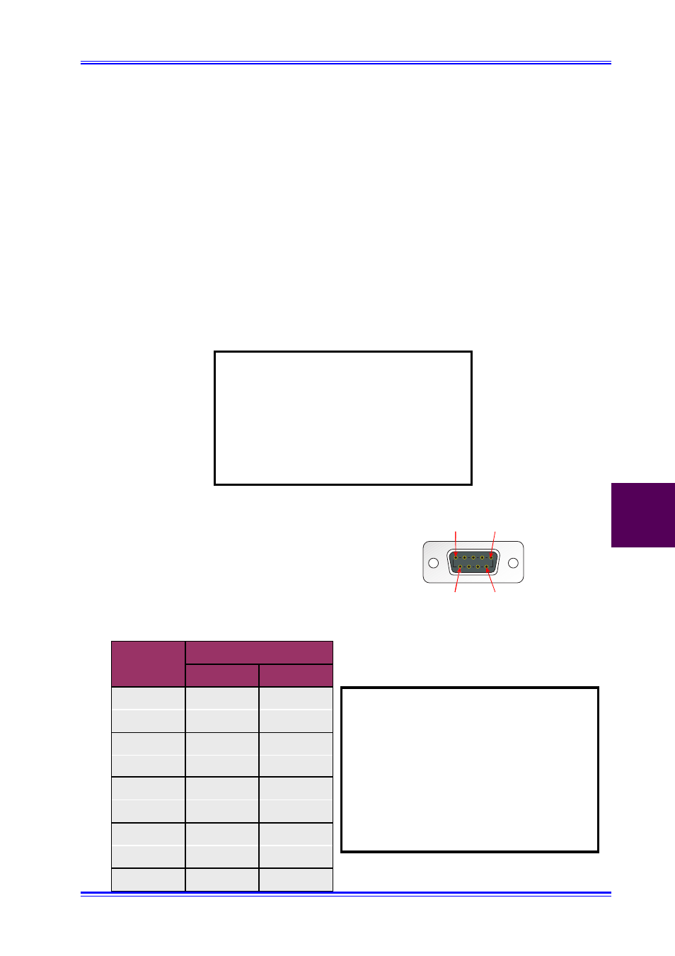
A2.1 COM1 & COM2 Interfaces
The two COM ports feature a complete set of handshaking and modem control signals, maskable
interrupt generation and highspeed data transfer rates. The selection between the RS232 and
RS485 serial data communication standard is performed via J1 & J2 (COM1, COM2) illustrated in
Figure A1.2.
Note:
If the COM ports are used in rear I/O
applications then they should not be
used from the CPU front-panel.
The front panel COM port connections
are disabled automatically if using the
rear I/O COM port option.
Figure A2.1 COM1 & COM2 Interface Pinout
1
6
5
9
Table A2.1 COM1 & COM2 Connector Signals
Note:
The standard CPU configuration has both
COM ports set for RS232 communication.
However, this device can be configured to
observe a two-wire, non galvanically
separated, RS485 protocol. The data
direction is governed by controlling the
UART’s RTS signal.
RS232
RS485
1
DCD
2
RxD
RxD, TxD +
3
TxD
RxD, TxD -
4
DTR
5
GND
6
DSR
7
RTS
8
CTS
9
RI
Pin No.
Signal