C1.5 lpt1 interface, Figure c1.5 lpt1 interface pinout, Table c1.5 lpt1 connector signals – Inova PD00941013.001 User Manual
Page 77: Compactpci, Itm-rio, Appendix c
©2004 Inova Computers GmbH
Page C-7
ICP-P4/PM/CM Appendix-C
Appendix C
ITM-RIO
CompactPCI
®
C
C1.5 LPT1 Interface
The physical LPT1 interface of the rear I/O panel illustrated in Figure C1.2 connects to J9 on the
baseboard for.
Note:
If the LPT port is used in rear I/O
applications then it should not be
used from the front-panel. Communi-
cating from both sources is physically
possible but is not recommended!
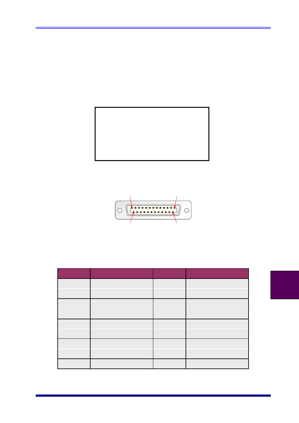
Figure C1.5 LPT1 Interface Pinout
Table C1.5 LPT1 Connector Signals
1
13
14
25
Pin No.
Signal
Pin No.
Signal
1
STROBE
2
PD0
3
PD1
4
PD2
5
PD3
6
PD4
7
PD5
8
PD6
9
PD7
10
ACK
11
BUSY
12
PE
13
SLCT
14
AUTOFD
15
ERROR
16
INIT
17
SLCTIN
18-25
GND