HP AMD Geode ECM-5510 User Manual
Page 51
User’s Manual
ECM-5510 User’s Manual
51
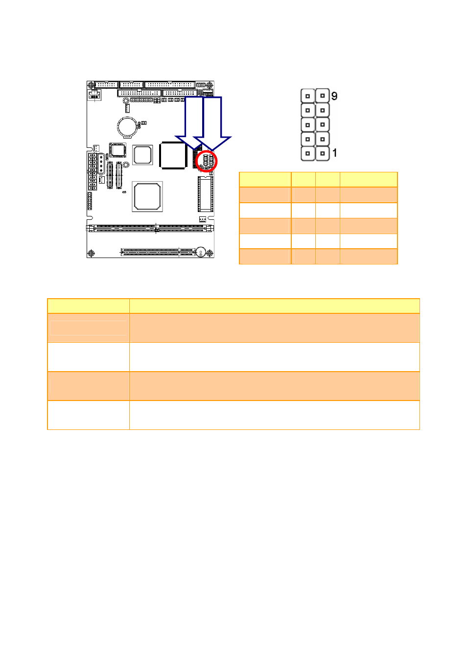
2.4.22
USB Connector 0, 1, 2 & 3 (CN12, CN15)
Signal
PIN
PIN
Signal
+5V
10
9
NC
D0-/D2- 8 7 GND
D0+/D2+
6
5
D1+/D3+
GND 4
3 D1-/D3-
GND
2
1
+5V
2.4.22.1 Signal
Description – USB Connector 0, 1, 2, 3 (CN12, CN15)
Signal
Signal Description
D0+ / D0-
Differential bi-directional data signal for USB channel 0. Clock is transmitted along
with the data using NRZI encoding. The signalling bit rate is up to 12 Mbs.
D1+ / D1-
Differential bi-directional data signal for USB channel 1. Clock is transmitted along
with the data using NRZI encoding. The signalling bit rate is up to 12 Mbs.
D2+ / D2-
Differential bi-directional data signal for USB channel 2. Clock is transmitted along
with the data using NRZI encoding. The signalling bit rate is up to 12 Mbs.
D3+ /D3-
Differential bi-directional data signal for USB channel 3. Clock is transmitted along
with the data using NRZI encoding. The signalling bit rate is up to 12 Mbs.
CN12
CN15