En g li s h – HP D3604-90004 User Manual
Page 21
2 Cabling Storage Devices and Setting SCSI Addresses
15
En
g
li
s
h
The switch setting location and functions are the same on both cages. The
switch 6 setting differentiates the upper and lower cages.
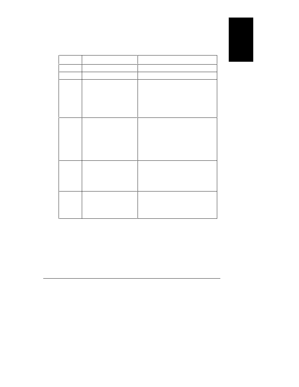
Table 2-1. Switch Functions and Settings
Switch
Functions
Settings
1
Not Used
Always set to Off.
2
Not Used
Always set to Off.
3
High/Low Addresses
Fast-Wide (68 pin)
SCSI Only.
Sets SCSI addresses for
upper or lower eight
addresses.
On
Sets the drives to the upper eight
SCSI addresses.
Off
Sets the drives to the lower eight
SCSI addresses.
See SCSI Address Settings table
below for description of the settings.
4
SCSI Address Zero
Sets middle shelf in the
hot-swap cage to SCSI ID 0
or ID 8. The ID number
depends on the setting of
switch 3.
On
Sets the middle shelf in the cage
(shelf 2 or shelf 5) to SCSI ID 0 or
SCSI ID 8.
Off
Sets the middle shelf to the
normal SCSI address sequence.
See SCSI Address Settings table below
for a description of the settings.
5
Remote Start
Determines control of the
hot-swap disk module
power-on sequence.
On
Internal control: Upper cage is set
to delayed start and lower cage is
set to power-on at startup.
Off
Power-on sequence is determined
by the host.
6
Upper/Lower Cage
Identifies cage location.
On
Lower cage.
Off
Upper cage.
See SCSI Address Settings table below
for description of settings.
It is important that the disk drives have a staggered power-up sequence. The
storage system may shut down if all of the devices attempt to spin-up at the same
time. If the staggered power-up sequence is not supported by the host system, be
sure switch 5 is in the “ON” (default) position.