Setting scsi addresses – HP D3604-90004 User Manual
Page 20
2 Cabling Storage Devices and Setting SCSI Addresses
14
Setting SCSI Addresses
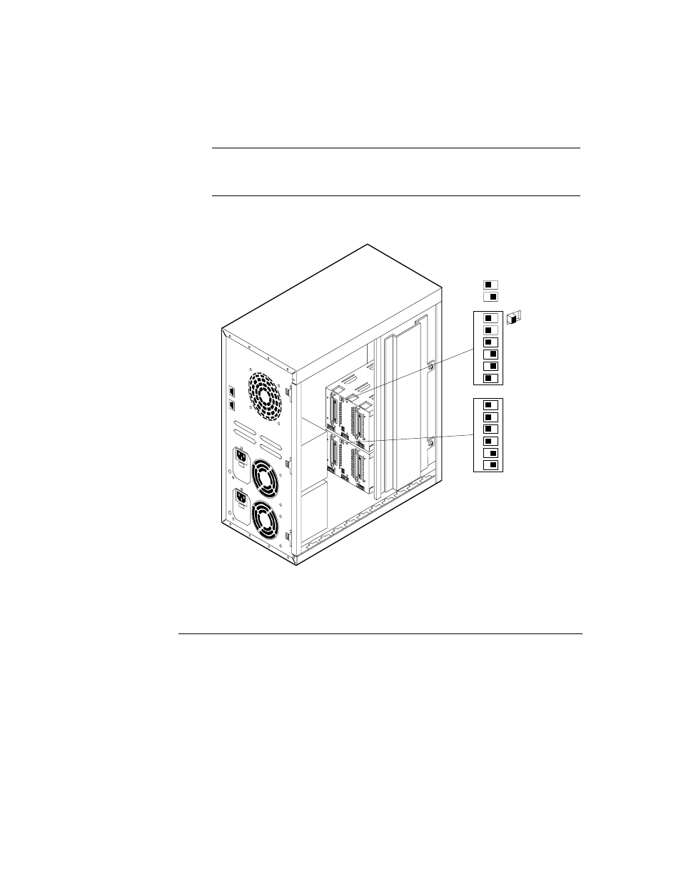
The following is a description of the switch settings on the rear of the hot-swap
subsystem cage (see Figure 2-1). The default switch setting is described in the
“Cabling Configurations” section of this chapter.
NOTE
The numbers on the front bezel simply denote the position of the
disk module in relation to the hot-swap subsystem. These numbers
are not related to the SCSI addresses.
Switches 3, 4 and 6 determine the SCSI address of the hot-swap shelf, as shown
in Figure 2-2.
UPPER
CAGE
LOWER
CAGE
Off
On
1
2
3
4
5
6
1
2
3
4
5
6
Figure 2-2. Storage System Switch Location
See also other documents in the category HP Hardware:
- NRM42 (61 pages)
- ProLiant ML370 (50 pages)
- ProLiant ML370 (49 pages)
- ProLiant ML110 G5 (32 pages)
- PC Comm Station Pro 304251-008 (North America) (5 pages)
- 100B-TX (32 pages)
- 3C905B-TX (110 pages)
- EK-STWCT-UG. E01 (45 pages)
- 3800ux (13 pages)
- 5991-6764 (8 pages)
- LTO 4 FC (46 pages)
- StorageWorks Network Attached Storage X3000 (16 pages)
- Ultrium Drive (30 pages)
- ProLiant DL360 (49 pages)
- CD Leycom CFL-512 (5 pages)
- RDX160 (12 pages)
- 345524-B21 (54 pages)
- DT-20 (20 pages)
- SureStore 7115w (136 pages)
- HD1600 (2 pages)
- ProLiant DL160 (38 pages)
- Vectra XW (16 pages)
- D2D4004i (20 pages)
- F1588A (4 pages)
- 94500 (1 page)
- Computer Parts (21 pages)
- MSA50 (8 pages)
- 7750 (32 pages)
- Media Gateways G350 (76 pages)
- P400 Serial (9 pages)
- MSL4048 (4 pages)
- 3C590-TPO (40 pages)
- mv2040 (2 pages)
- AHA-8940 (82 pages)
- ProLiant DL385 (47 pages)
- ProLiant DL385 (174 pages)
- 5300A (19 pages)
- AMD Geode E2047551001R (111 pages)
- 1100d (102 pages)
- Reliable Transaction Router (100 pages)
- xp1024 (2 pages)
- 180 Degree Turn (24 pages)
- procurve J8165A (32 pages)
- 04H8095 (28 pages)
- 744 (154 pages)