E. vent diagrams, Top vent - horizontal termination – Heat & Glo Fireplace LUX60 User Manual
Page 28
Heat & Glo • LUX60 • 4062-116 • Rev. G • 4/11
28
H
1
V
1
To replace the fi rst starter elbow with two 45° elbows,
refer to Figure 7.4. All other 90° elbows can be replaced
with two 45° elbows.
General Rules:
•
SUBTRACT 3 ft. from the total H measurement for each
90° elbow installed horizontally.
• SUBTRACT 1-1/2 ft. from the total H measurement for
each 45° elbow installed horizontally.
• A maximum of three 90° elbows (or six 45° elbows)
may be used in any vent confi guration.
NOTICE:
DO NOT install elbows horizontally.
• Elbows may be placed back to back anywhere in the
system as long as the fi rst 90° elbow is a starter elbow
except as shown in Figure 7.4.
• When penetrating a combustible wall, a wall shield
fi restop must be installed.
• When penetrating a combustible ceiling, a ceiling
fi restop must be installed.
• Horizontal runs of vent do not require vertical rise;
horizontal runs may be level.
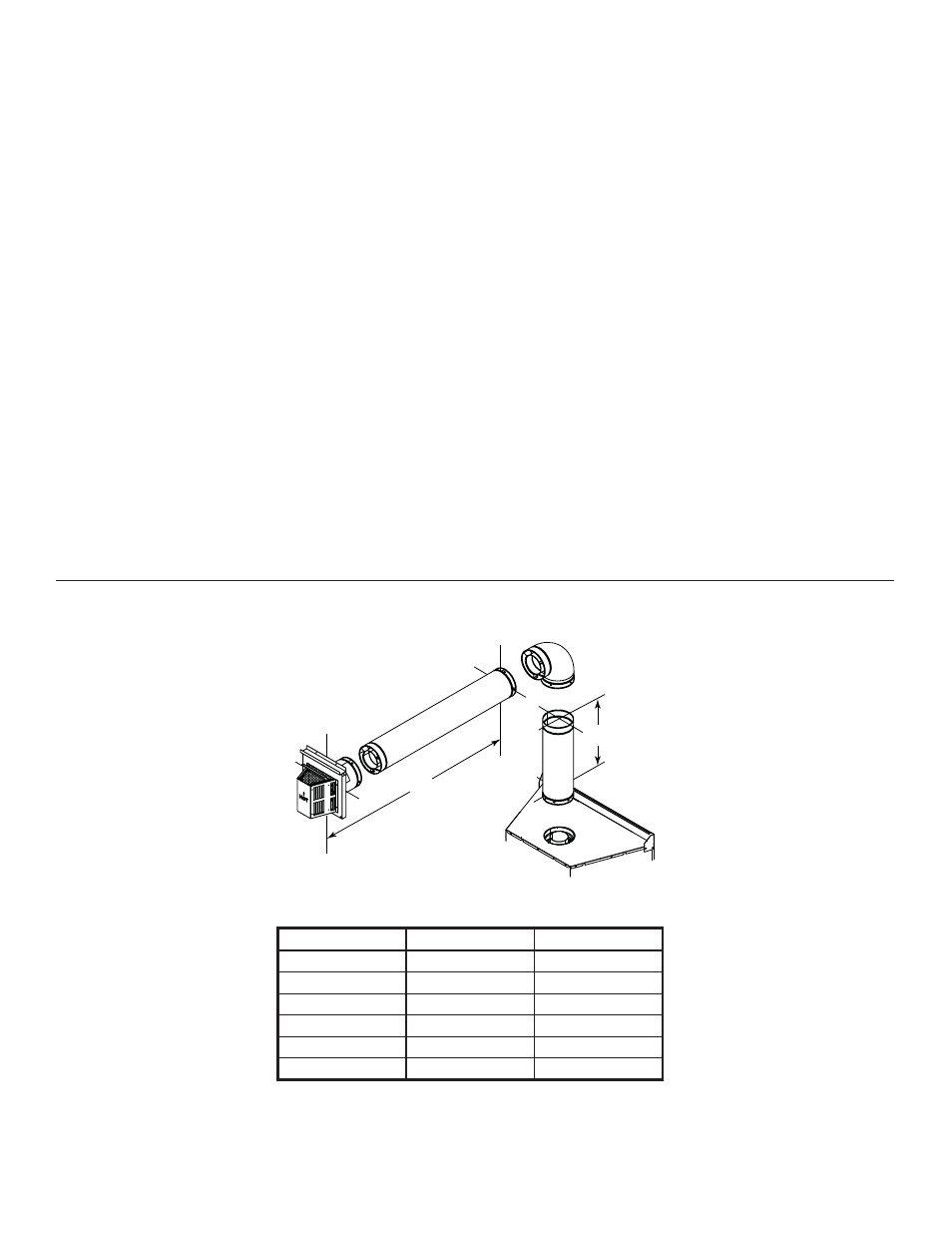
E. Vent Diagrams
Figure 7.3
One Elbow
1. Top Vent - Horizontal Termination
V
1
Min.
V
1
Max.
H
1
Max.
3 ft (.91 m)
-
1.5 ft (.46 m)
4 ft (1.22 m)
-
6 ft (1.83 m)
5 ft (1.52)
-
11 ft (3.35 m)
6 ft (1.83 m)
-
13 ft (3.96 m)
7 ft (2.13 m)
-
15 ft (4.57 m)
10 ft (3.05 m)
25 ft (7.62 m)
20 ft (6.10 m)