HP 3150 EN User Manual
Page 103
EN
Document scanner assemblies 101
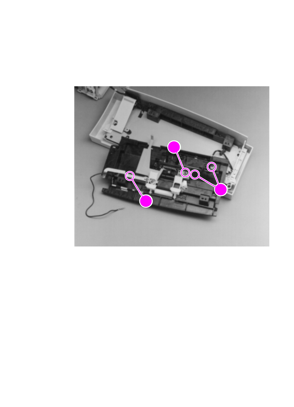
4
Remove the screw (callout 1) from one of the small printed circuit
boards.
5
On all HP LaserJet 3150 products and on some HP LaserJet
3100 products, there is an additional screw (callout 2) to remove.
6
Release two (2) cables (callout 3) from their connectors, one on
each of the small printed circuit boards.
Figure 29. Upper guide assembly removal (2 of 2)
To reinstall
Make sure that the assembly is inserted correctly into the three
notches.
2
2
1
3
2
2
This manual is related to the following products:
See also other documents in the category HP Printers:
- Laserjet p1606dn (152 pages)
- LaserJet 1320 (184 pages)
- LaserJet 1320 (4 pages)
- LaserJet 1320 (2 pages)
- LaserJet 1320 (9 pages)
- Deskjet 6940 (150 pages)
- LaserJet P2035n (148 pages)
- LaserJet 4250 (304 pages)
- LaserJet P2055dn (176 pages)
- Deskjet 5650 (165 pages)
- LASERJET PRO P1102w (158 pages)
- LaserJet P2015 (158 pages)
- DesignJet 500 (16 pages)
- DesignJet 500 (268 pages)
- Officejet Pro 8000 - A809 (140 pages)
- Officejet 6100 (138 pages)
- Officejet 6000 (168 pages)
- LASERJET PRO P1102w (2 pages)
- 2500c Pro Printer series (66 pages)
- 4100 mfp (164 pages)
- 3600 Series (6 pages)
- 3392 (10 pages)
- LASERJET 3800 (18 pages)
- 3500 Series (4 pages)
- Photosmart 7515 e-All-in-One Printer - C311a (62 pages)
- PSC-500 (40 pages)
- 2500C/CM (65 pages)
- QMS 4060 (232 pages)
- 2280 (2 pages)
- 2430dtn (4 pages)
- 1500 (13 pages)
- 1000 Series (1 page)
- TOWERFEED 8000 (36 pages)
- Deskjet 3848 Color Inkjet Printer (95 pages)
- 2100 TN (184 pages)
- B209 (24 pages)
- Designjet 100 Printer series (1 page)
- QM2-111 (35 pages)
- 2100 (5 pages)
- 2000CP series (2 pages)
- 2300L (4 pages)
- 35000 (2 pages)
- 3015 (2 pages)
- Color LaserJet CM3530 Multifunction Printer series (302 pages)
- StudioJet (71 pages)