5installation, 48 / 63 fr, 2 types d’installation (choisissez a, b ou c) – Beko 30 Inch Over the Range Convection Microwave Installation Guide User Manual
Page 48: Recyclage d’air (type c - évacuation sans conduit)
Four à micro-ondes à convection à hotte intégrée / Manuel d’installation
48 / 63 FR
5
Installation
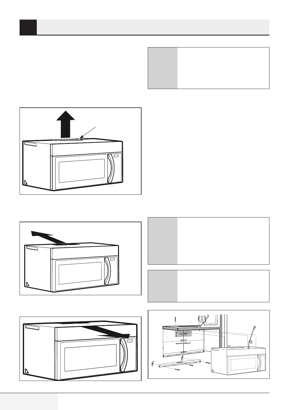
5.2 Types d’installation
(choisissez A, B ou C)
Ce four à micro-ondes est conçu pour s’adapter
aux trois types d’évacuation suivants :
•
Évacuation à l’extérieur par le dessus (Type A -
conduit vertical)
Adaptateur en place
pour une évacuation
à l’extérieur par le dessus
•
Évacuation à l’extérieur par l’arrière (Type B -
conduit horizontal)
Placez l'adaptateur à
l’arrière pour une évacuation
à l’extérieur par l’arrière.
•
Recyclage d’air (Type C - évacuation sans
conduit)
C
Ce four à micro-ondes est équipé
à l’usine en vue d’un Recyclage.
Choisissez le type d’évacuation ap-
proprié à votre installation et ren-
dez-vous à cette section.
5.2.1 Évacuation à l’extérieur
par le dessus (Type A - conduit
vertical)
Vue d’ensemble de l’installation
A1 : Fixation de la plaque de montage au mur
A2 : Préparation de l’armoire supérieure
A3 : Adaptation du ventilateur du four à micro-
ondes pour
A4 : Vérification du fonctionnement du registre
A5 : Installation du four à micro-ondes
A6 : Ajustement de l’adaptateur d’évacuation
A7 : Connexion au conduit
A
Assurez-vous que les vis du moteur
du ventilateur et de la plaque du
ventilateur sont correctement ser-
rées lorsque vous les remettez en
place. Cela permet d’éviter des vibra-
tions excessives.
A
Assurez-vous que le câblage du mo-
teur a été effectué et correctement
fixé, et que les câbles ne sont pas
coincés.
3/8" TO EDGE
NOTE: IT IS VERY IMPORTANT TO
READ AND FOLLOW THE DIRECTIO
NS
IN THE INSTALLATION INSTRU
CTIONS
BEFORE PROCEEDING WITH
THIS
REAR WALL TEMPLATE.
This Rear Wall Template serves to p
osition the bottom
mounting plate and to locate the h
orizontal exhaust
outlet.
1. Use a level to check that the tem
plate is positioned
accurately.
2. Locate and mark at least one stu
d on the left or
right side of the centerline.
It is important to use at least one wo
od
screw mounted firmly in a stud to sup
port the weight
of the microwave. Mark two addition
al, evenly spaced
locations for the supplied toggle bol
ts.
3. Drill holes in the marked locatio
ns. Where there is
a stud, drill a 3/16" hole for woo
d screws. For holes
that do not line up with a stud, d
rill 5/8" holes for
toggle bolts.
DO NOT INSTALL THE MOUNTIN
G PLATE
AT THIS TIME.
4. Remove the template from the r
ear wall.
5. Review the Installation Instructio
n book for your
installation situation.
Locate and mark holes to align with holes
in the
mounting plate.
IMPORTANT:
LOCATE AT LEAST ONE STUD
ON EITHER SIDE OF
THE CENTERLINE.
MARK THE LOCATION FOR 2 ADDIT
IONAL, EVENLY
SPACED TOGGLE BOLTS IN THE MO
UNTING PLATE
AREA.
Locate and mark holes to align
with holes in the
mounting plate.
IMPORTANT:
LOCATE AT LEAST ONE STUD
ON EITHER SIDE OF
THE CENTERLINE.
MARK THE LOCATION FOR 2
ADDITIONAL, EVENLY
SPACED TOGGLE BOLTS IN
THE MOUNTING PLATE
AREA.
Trim the rear wall template along
the dotted line.
Trim the rear wall template along
the dotted line.
12"
4"
Darle vuelta a la hoja para cons
ultar la
versión en Español.