5installation, 47 / 63 fr, 4 alignement de la plaque murale – Beko 30 Inch Over the Range Convection Microwave Installation Guide User Manual
Page 47: Ne fixez pas la plaque de montage maintenant
Four à micro-ondes à convection à hotte intégrée / Manuel d’installation
47 / 63 FR
Area E
Trou A
Trou B
B
Encoches de
la ligne centrale
Tracez une ligne verticale
sur le mur à partir du
centre de l'armoire supérieure.
Tracez une ligne horizontale sur le mur
à partir du « gabarit pour mur arrière ».
Ligne horizontale
Ligne horizontale
CL
3/8" TO EDGE
NOTE: IT IS VERY IMPORTANT TO
READ AND FOLLOW THE DIRECTIONS
IN THE INSTALLATION INSTRUCTIONS
BEFORE PROCEEDING WITH THIS
REAR WALL TEMPLATE.
This Rear Wall Template serves to position the bottom
mounting plate and to locate the horizontal exhaust
outlet.
1. Use a level to check that the template is positioned
accurately.
2. Locate and mark at least one stud on the left or
right side of the centerline.
It is important to use at least one wood
screw mounted firmly in a stud to support the weight
of the microwave. Mark two additional, evenly spaced
locations for the supplied toggle bolts.
3. Drill holes in the marked locations. Where there is
a stud, drill a 3/16" hole for wood screws. For holes
that do not line up with a stud, drill 5/8" holes for
toggle bolts.
DO NOT INSTALL THE MOUNTING PLATE
AT THIS TIME.
4. Remove the template from the rear wall.
5. Review the Installation Instruction book for your
installation situation.
Locate and mark holes to align with holes in the
mounting plate.
IMPORTANT:
LOCATE AT LEAST ONE STUD ON EITHER SIDE OF
THE CENTERLINE.
MARK THE LOCATION FOR 2 ADDITIONAL, EVENLY
SPACED TOGGLE BOLTS IN THE MOUNTING PLATE
AREA.
Locate and mark holes to align with holes in the
mounting plate.
IMPORTANT:
LOCATE AT LEAST ONE STUD ON EITHER SIDE OF
THE CENTERLINE.
MARK THE LOCATION FOR 2 ADDITIONAL, EVENLY
SPACED TOGGLE BOLTS IN THE MOUNTING PLATE
AREA.
Trim the rear wall template along the dotted line.
12"
4"
Darle vuelta a la hoja para consultar la
versión en Español.
A
Portez des gants pour éviter de vous
blesser sur les bords coupants.
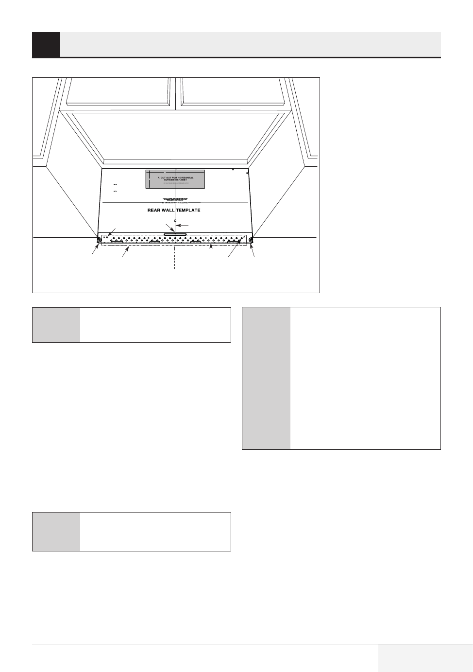
5.1.4 Alignement de la plaque
murale
1. Tracez une ligne verticale sur le mur au centre
de l’espace de 30 po de large.
2. Tracez une ligne horizontale sur le mur de fond
du « Gabarit pour mur arrière ».
3. Percez des trous de 5/8 po à deux endroits
(Trou A, Trou B). S’il y a un montant, percez un
trou de 3/16 po pour les vis à bois. En d’autres
mots, vous ne pouvez pas utiliser les boulons à
ailettes à l’emplacement d’un montant.
C
NE FIXEZ PAS LA PLAQUE DE
MONTAGE MAINTENANT.
5
Installation
C
Les trous A et B sont situés à l’inté-
rieur de la zone E. Si aucun des trous
A et B ne se trouvent dans un mon-
tant, trouvez un montant à un autre
endroit de la zone E et tracez un qua-
trième cercle aligné sur ce montant.
Il est important qu’au moins une vis
à bois soit bien fixée dans un mon-
tant pour soutenir le poids du micro-
ondes. Mettez la plaque de montage
de côté.