5installation, 15 / 63 en, 33" to cooktop – Beko 30 Inch Over the Range Convection Microwave Installation Guide User Manual
Page 15
15 / 63 EN
Over The Range Convection Microwave Oven / Installation Manual
5
Installation
33
ʺ
to Cooktop
Draw a vertical line on the wall at the center of the
30
ʺ
space.
Tape the Rear Wall Template onto the wall
matching the centerline and touching the bottom
cabinet frame.
CL
3/8" TO EDGE
NOTE: IT IS VER
Y IMPORTANT T
O
READ AND FOLL
OW THE DIRECT
IONS
IN THE INSTALL
ATION INSTRUC
TIONS
BEFORE PROCE
EDING WITH TH
IS
REAR WALL TEM
PLATE.
This Rear Wall Tem
plate serves to posit
ion the bottom
mounting plate and
to locate the horizon
tal exhaust
outlet.
1. Use a level to che
ck that the template
is positioned
accurately.
2. Locate and mark
at least one stud on
the left or
right side of the cen
terline.
It is important to use
at least one wood
screw mounted firm
ly in a stud to suppo
rt the weight
of the microwave. M
ark two additional, e
venly spaced
locations for the sup
plied toggle bolts.
3. Drill holes in the
marked locations. W
here there is
a stud, drill a 3/16
" hole for wood scre
ws. For holes
that do not line up
with a stud, drill 5/8
" holes for
toggle bolts.
DO NOT INSTALL
THE MOUNTING P
LATE
AT THIS TIME.
4. Remove the tem
plate from the rear w
all.
5. Review the Install
ation Instruction boo
k for your
installation situation
.
Locate and mark
holes to align with
holes in the
mounting plate.
IMPORTANT:
LOCATE AT LEA
ST ONE STUD ON
EITHER SIDE OF
THE CENTERLIN
E.
MARK THE LOC
ATION FOR 2 AD
DITIONAL, EVE
NLY
SPACED TOGGL
E BOLTS IN THE
MOUNTING PLA
TE
AREA.
Locate and mark
holes to align with
holes in the
mounting plate.
IMPORTANT:
LOCATE AT LEA
ST ONE STUD ON
EITHER SIDE OF
THE CENTERLIN
E.
MARK THE LOCA
TION FOR 2 ADD
ITIONAL, EVEN
LY
SPACED TOGGLE
BOLTS IN THE M
OUNTING PLATE
AREA.
Trim the rear wall
template along t
he dotted line.
Trim the rear wa
ll template along
the dotted line.
12"
4"
Darle vuelta a la h
oja para consultar
la
versión en Españo
l.
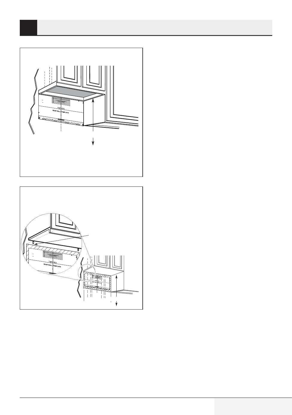
Plate position—beneath framed recessed
cabinet bottom
Draw a line on the
back wall equal to the
depth of the front
overhang.
33" to Cooktop
CL
3/8" TO EDGE
NOTE: IT IS VER
Y IMPORTANT T
O
READ AND FOL
LOW THE DIRE
CTIONS
IN THE INSTALL
ATION INSTRUC
TIONS
BEFORE PROC
EEDING WITH T
HIS
REAR WALL TE
MPLATE.
This Rear Wall Te
mplate serves to p
osition the bottom
mounting plate and
to locate the horizo
ntal exhaust
outlet.
1. Use a level to ch
eck that the templa
te is positioned
accurately.
2. Locate and mark
at least one stud o
n the left or
right side of the ce
nterline.
It is important to us
e at least one woo
d
screw mounted firm
ly in a stud to supp
ort the weight
of the microwave.
Mark two additiona
l, evenly spaced
locations for the su
pplied toggle bolts
.
3. Drill holes in the
marked locations.
Where there is
a stud, drill a 3/16"
hole for wood scre
ws. For holes
that do not line up
with a stud, drill 5/8
" holes for
toggle bolts.
DO NOT INSTALL
THE MOUNTING
PLATE
AT THIS TIME.
4. Remove the tem
plate from the rear
wall.
5. Review the Insta
llation Instruction
book for your
installation situatio
n.
Locate and ma
rk holes to align
with holes in the
mounting plate.
IMPORTANT:
LOCATE AT LEA
ST ONE STUD
ON EITHER SID
E OF
THE CENTERLIN
E.
MARK THE LOC
ATION FOR 2 A
DDITIONAL, EV
ENLY
SPACED TOGG
LE BOLTS IN TH
E MOUNTING P
LATE
AREA.
Locate and mark
holes to align with
holes in the
mounting plate.
IMPORTANT:
LOCATE AT LEA
ST ONE STUD O
N EITHER SIDE
OF
THE CENTERLIN
E.
MARK THE LOC
ATION FOR 2 A
DDITIONAL, EV
ENLY
SPACED TOGG
LE BOLTS IN TH
E MOUNTING P
LATE
AREA.
Trim the rear w
all template alon
g the dotted lin
e.
Trim the rear w
all template alo
ng the dotted lin
e.
12"
4"
Darle vuelta a la
hoja para consult
ar la
versión en Españ
ol.
3/8" TO EDGE
NOTE: IT IS V
ERY IMPOR
TANT TO
READ AND FO
LLOW THE DIR
ECTIONS
IN THE INSTALL
ATION INSTRUC
TIONS
BEFORE PROC
EEDING WITH
THIS
REAR WALL T
EMPLATE.
This Rear Wall Temp
late serves to posit
ion the bottom
mounting plate and
to locate the horiz
ontal exhaust
outlet.
1. Use a level to
check that the temp
late is positioned
accurately.
2. Locate and mar
k at least one stud
on the left or
right side of the c
enterline.
It is important to us
e at least one woo
d
screw mounted firmly
in a stud to supp
ort the weight
of the microwave. Ma
rk two additional, e
venly spaced
locations for the sup
plied toggle bolts.
3. Drill holes in the
marked locations. W
here there is
a stud, drill a 3/1
6" hole for wood scr
ews. For holes
that do not lin
e up with a stud,
drill 5/8" holes fo
r
toggle bolts.
DO NOT INST
ALL THE MOUNTIN
G PLATE
AT THIS TIME
.
4. Remove the temp
late from the rear w
all.
5. Review the Insta
llation Instruction
book for your
installation situ
ation.
Locate and ma
rk holes to align w
ith holes in the
mounting plate.
IMPORTANT:
LOCATE AT LEAST
ONE STUD ON EIT
HER SIDE OF
THE CENTERLIN
E.
MARK THE LOCAT
ION FOR 2 AD
DITIONAL, EVEN
LY
SPACED TOGG
LE BOLTS IN TH
E MOUNTING PL
ATE
AREA.
Locate and ma
rk holes to align w
ith holes in the
mounting plate.
IMPORTANT:
LOCATE AT
LEAST ONE ST
UD ON EITHER
SIDE OF
THE CENTERLIN
E.
MARK THE LO
CATION FOR 2
ADDITIONAL, EV
ENLY
SPACED TOGG
LE BOLTS IN TH
E MOUNTING P
L
AREA.
Trim the rear w
all template alon
g the dotted
line.
Trim the rear
wall template alon
g the dotted line.
12"
4"
Darle vuelta a la
hoja para consult
ar la
versión en Españ
ol.
Plate position—beneath recessed bottom
cabinet with front overhang
Your cabinets may have decorative trim that inter-
feres with the microwave installation. Remove the
decorative trim to install the microwave properly
and to make it level
The microwave must be level.
Use a level to make sure the cabinet bottom is lev-
el.
If the cabinets have a front overhang only, with
no back or side frame, install the mounting plate
down the same distance as the front overhang
depth. This will keep the microwave level.
1. Measure the inside depth of the front overhang.
2. Draw a horizontal line on the back wall an equal
distance below the cabinet bottom as the inside
depth of the front overhang.
3. For this type of installation with front overhang
only, align the mounting tabs with this
horizontal line, not touching the cabinet bottom
as described in subtitle 5.1.4.