5installation, 17 / 63 en, 2 installation types (choose a, b or c) – Beko 30 Inch Over the Range Convection Microwave Installation Guide User Manual
Page 17: 1 outside top exhaust (vertical duct type a), Outside back exhaust (horizontal duct type b), Recirculating (non-vented ductless type c), Adaptor in place for outside top exhaust
17 / 63 EN
Over The Range Convection Microwave Oven / Installation Manual
5
Installation
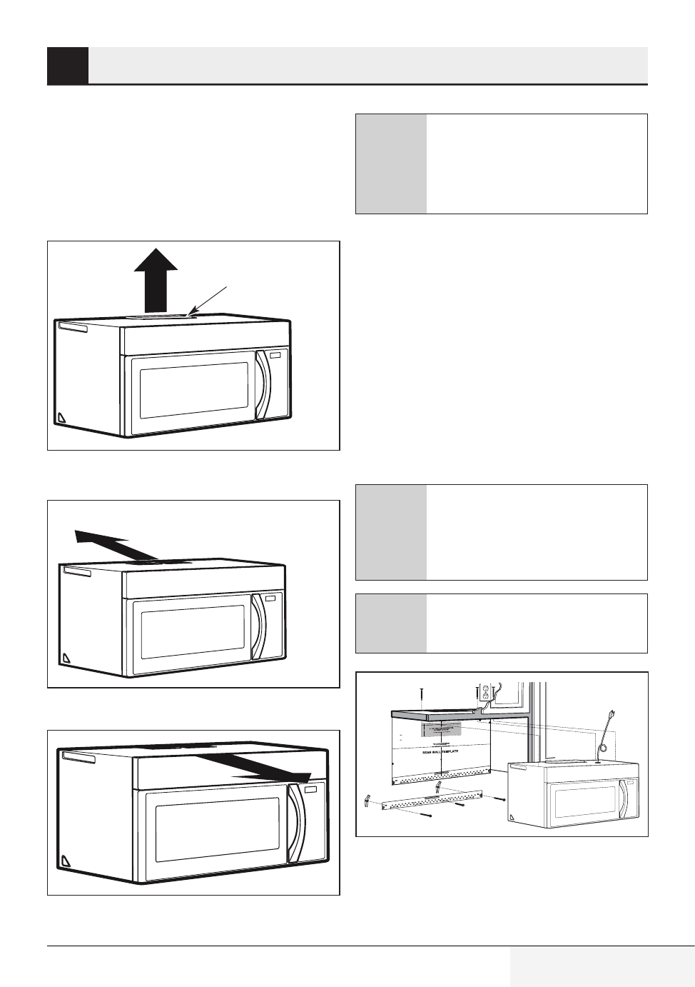
5.2 Installation types (choose
A, B or C)
this microwave oven is designed for adaptation to
the following three types of ventilation:
•
Outside Top Exhaust (Vertical Duct Type A)
Adaptor in Place for
Outside Top Exhaust
•
Outside Back Exhaust (Horizontal Duct Type B)
Adaptor Must Be
Moved to the Back for
Outside Back Exhaust
•
Recirculating (Non-Vented Ductless Type C)
C
This microwave is shipped assem-
bled for Recirculating. Select the
type of ventilation required for your
installation and proceed to that sec-
tion.
5.2.1 Outside top exhaust
(vertical duct type A)
installation overview
A1. Attach Mounting Plate to Wall
A2. Prepare Top Cabinet
A3. Adapting Microwave Blower for
A4. Check Damper Operation
A5. Mount Microwave Oven
A6. Adjust Exhaust Adaptor
A7. Connect Ductwork
A
Make sure the screws for the blower
motor and blower plate are securely
tightened when they are reinstalled.
This will help to prevent excessive
vibration.
A
Make sure the motor wiring has
been properly routed and secured,
and that the wires are not pinched.
3/8" TO EDGE
NOTE: IT IS VERY IMPORTANT TO
READ AND FOLLOW THE DIRECTIO
NS
IN THE INSTALLATION INSTRU
CTIONS
BEFORE PROCEEDING WITH
THIS
REAR WALL TEMPLATE.
This Rear Wall Template serves to p
osition the bottom
mounting plate and to locate the h
orizontal exhaust
outlet.
1. Use a level to check that the tem
plate is positioned
accurately.
2. Locate and mark at least one stu
d on the left or
right side of the centerline.
It is important to use at least one wo
od
screw mounted firmly in a stud to sup
port the weight
of the microwave. Mark two addition
al, evenly spaced
locations for the supplied toggle bol
ts.
3. Drill holes in the marked locatio
ns. Where there is
a stud, drill a 3/16" hole for woo
d screws. For holes
that do not line up with a stud, d
rill 5/8" holes for
toggle bolts.
DO NOT INSTALL THE MOUNTIN
G PLATE
AT THIS TIME.
4. Remove the template from the r
ear wall.
5. Review the Installation Instructio
n book for your
installation situation.
Locate and mark holes to align with holes
in the
mounting plate.
IMPORTANT:
LOCATE AT LEAST ONE STUD
ON EITHER SIDE OF
THE CENTERLINE.
MARK THE LOCATION FOR 2 ADDIT
IONAL, EVENLY
SPACED TOGGLE BOLTS IN THE MO
UNTING PLATE
AREA.
Locate and mark holes to align
with holes in the
mounting plate.
IMPORTANT:
LOCATE AT LEAST ONE STUD
ON EITHER SIDE OF
THE CENTERLINE.
MARK THE LOCATION FOR 2
ADDITIONAL, EVENLY
SPACED TOGGLE BOLTS IN
THE MOUNTING PLATE
AREA.
Trim the rear wall template along
the dotted line.
Trim the rear wall template along
the dotted line.
12"
4"
Darle vuelta a la hoja para cons
ultar la
versión en Español.