5installation, 23 / 63 en, 2 outside back exhaust (horizontal duct type b) – Beko 30 Inch Over the Range Convection Microwave Installation Guide User Manual
Page 23
23 / 63 EN
Over The Range Convection Microwave Oven / Installation Manual
5
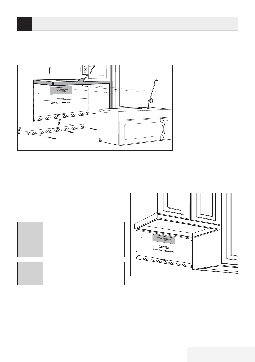
Installation
5.2.2 Outside back exhaust
(horizontal duct type B)
3/8" TO EDGE
NOTE: IT IS VERY IMPORTANT TO
READ AND FOLLOW THE DIRECTIO
NS
IN THE INSTALLATION INSTRU
CTIONS
BEFORE PROCEEDING WITH
THIS
REAR WALL TEMPLATE.
This Rear Wall Template serves to
position the bottom
mounting plate and to locate the h
orizontal exhaust
outlet.
1. Use a level to check that the templa
te is positioned
accurately.
2. Locate and mark at least one st
ud on the left or
right side of the centerline.
It is important to use at least one wo
od
screw mounted firmly in a stud to sup
port the weight
of the microwave. Mark two addition
al, evenly spaced
locations for the supplied toggle bo
lts.
3. Drill holes in the marked locatio
ns. Where there is
a stud, drill a 3/16" hole for woo
d screws. For holes
that do not line up with a stud, d
rill 5/8" holes for
toggle bolts.
DO NOT INSTALL THE MOUNTIN
G PLATE
AT THIS TIME.
4. Remove the template from the r
ear wall.
5. Revie h
t
w e Installation Instruction book
for your
installation situation.
Locate and mark holes to align wi
th holes in the
mounting plate.
IMPORTANT:
LOCATE AT LEAST ONE STUD
ON EITHER SIDE OF
THE CENTERLINE.
MARK THE LOCATION FOR 2 ADDI
TIONAL, EVENLY
SPACED TOGGLE BOLTS IN THE MO
UNTING PLATE
AREA.
Locate and mark holes to align w
ith holes in the
.
e
t
a
l
p
g
n
it
n
u
o
m
IMPORTANT:
LOCATE AT LEAST ONE STUD
ON EITHER SIDE OF
THE CENTERLINE.
MARK THE LOCATION FOR 2 ADD
ITIONAL, EVENLY
SPACED TOGGLE BOLTS IN
THE MOUNTING PLATE
AREA.
Trim the rear wall template along
the dotted line.
Trim the rear wall template al
ong the dotted line.
12"
4"
Darle vuelta a la hoja para cons
ultar la
versión en Español.
Installation overview
B1. Prepare Rear Wall
B2. Remove Blower Plate
B3. Attach Mounting Plate to Wall
B4. Prepare Top Cabinet
B5. Adjust Blower
B6. Mount the Microwave Oven
A
Make sure the screws for the blower
motor and blower plate are securely
tightened when they are reinstalled.
This will help to prevent excessive
vibration.
A
Make sure the motor wiring has
been properly routed and secured,
and that the wires are not pinched.
B1. Preparing the rear wall for out-
side back exhaust
You need to cut an opening in the rear wall for out-
side exhaust.
3/8" TO EDGE
NOTE: IT IS VE
RY IMPOR
TANT TO
READ AND FOLL
OW THE DIRECTI
ONS
IN THE INSTA
L
S
N
I
N
O
I
T
A
L
TRUCTIONS
BEFORE PR
OCEEDING WI
TH THIS
REAR WALL TEMP
LATE.
This Rear Wall Te
mplate serves to p
osition the bottom
mounting plate and
to locate the horiz
ontal exhaust
outlet.
1. Use a level to ch
eck that the templa
te is positioned
accurately.
2. Locate and mar
k at least one stud
on the left or
right side of the ce
nterline.
It is important to us
e at least one woo
d
screw mounted firmly
in a stud to support
the weight
of the microwave.
Mark two additiona
l, evenly spaced
locations for the supplied
toggle bolts.
3. Drill holes in the
marked locations
. Where there is
a stud, drill a 3/16"
hole for wood screws.
For holes
that do not line up
with a stud, drill 5/8
" holes for
toggle bolts.
DO NOT INSTALL
THE MOUNT
ING PLATE
AT THIS TIME.
4. Remove the tem
plate from the rear
wall.
5. Review the Ins
tallation Instruction
book for your
installation situatio
n.
Locate and mar
k holes to align
with holes in the
mounting plate.
IMPORTANT:
LOCATE
AT LEAST ON
E STUD ON EITH
ER SIDE OF
THE CENTERLINE
.
MARK THE LOC
ATION FOR
2 ADDITIONAL
, EVENLY
SPACED TOGG
LE BOLTS IN
THE MOUNTIN
G PLATE
AREA.
Locate and mar
k holes to align w
ith holes in the
mounting plate.
IMPORTA
NT:
LOCATE AT LE
AST ONE STUD O
N EITHER SI
DE OF
THE CENTER
LINE.
MARK TH
E LOCATION FOR
2 ADDITIONAL
, EVENLY
SPACED TOGG
LE BOLTS IN
THE MOUNTI
NG PLATE
AREA.
Trim the rear wa
ll template
along the d
otted line.
Trim the rear wall
template along
the dotted
line.
12"
4"
Darle vuelta a la
hoja para consul
tar la
versión en Españ
ol.
•
Read the instructions on the REAR WALL
TEMPLATE.
•
Tape it to the rear wall, lining up with the holes
previously drilled for holes A and B in the wall
plate.
•
Cut the opening, following the instructions of
the REAR WALL TEMPLATE.