Cable connection to lc fiber-optic connectors -31, Га в б – Enterasys Networks Enterasys SecureStack A2 A2H124-48P User Manual
Page 61
Installing Optional Mini-GBICs
SecureStack A2 PoE Installation Guide 3-31
1.
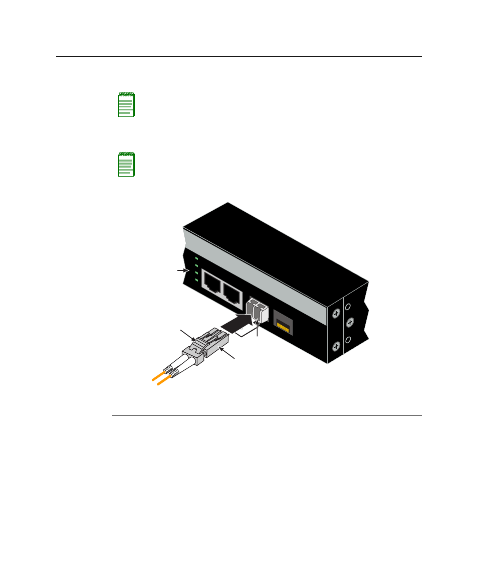
Remove the protective covers (not shown) from the front panel LC fiber‐optic port
(port 27 in this example) and from the connectors on each end of the cable.
2.
Insert the LC cable connector into the Mini‐GBIC LC connector until it clicks into
place.
Figure 3-21 Cable Connection to LC Fiber-Optic Connectors
3.
Plug the other end of the cable into the appropriate port on the other device. Some
cables may be terminated at the other end with two separate connectors, one for each
fiber‐optic strand. In this case, ensure that the transmit fiber‐optic strand is connected
to the receive port and the receive fiber‐optic strand to the transmit port.
Note: Leave the protective covers in place when the connectors are not in use to prevent
contamination.
Note: To remove the LC cable connector, press on its release tab and pull it out of
Mini-GBIC LC connector.
1 Mini-GBIC MT-RJ port connector
3 Release tab
2 LC cable connector
4 Link/Activity LED
27
28
A2H124-24P
Г
А
В
Б
25
26
27
28
25/Up
26/Do
wn
Stac
k