Adjusting universal interface feet, Install projector – Epson Universal Projector Mount with 3" Extension Column User Manual
Page 10
ELPMBPJG
Installation Instructions
10
Adjusting Universal Interface Feet
WARNING:
IMPROPER INSTALLATION CAN LEAD TO
PROJECTOR FALLING CAUSING SERIOUS PERSONAL
INJURY OR DAMAGE TO EQUIPMENT! DO NOT substitute
hardware. Use only hardware provided by the manufacturer
and make certain all hardware is properly tightened.
1.
Adjust the feet on the universal interface to the proper
height.
NOTE:
Foot height is adjusted for a variety of reasons
including: ventilation, uneven projector surface, or to
level the interface bracket mounting plate.
2.
Visually check the height of the mounting plate on the
interface.
3.
Loosen screw and adjust foot that is attached to adjustable
leg. The foot may be removed and reattached to allow more
adjustment, if necessary. (See Figure 15)
4.
Adjust foot height as needed. If necessary, use a level to
verify that the universal interface mounting plate is level.
5.
Tighten screw.
6.
Repeat procedure for each foot as needed until the feet on
the universal interface are adjusted properly.
Figure 15
Install Projector
WARNING:
IMPROPER INSTALLATION CAN LEAD TO
PROJECTOR FALLING RESULTING IN SERIOUS
PERSONAL INJURY OR DAMAGE TO EQUIPMENT. DO
NOT substitute hardware. Use only the hardware provided by
the manufacturer.
IMPORTANT ! :
For security attachment of projector,
proceed to
Step 1
. For easy-release attachment of
projector, proceed to
Step 2
.
1.
Remove two thumb nuts and Phillips screws from opposite
corners of universal interface. (See Figure 16)
Figure 16
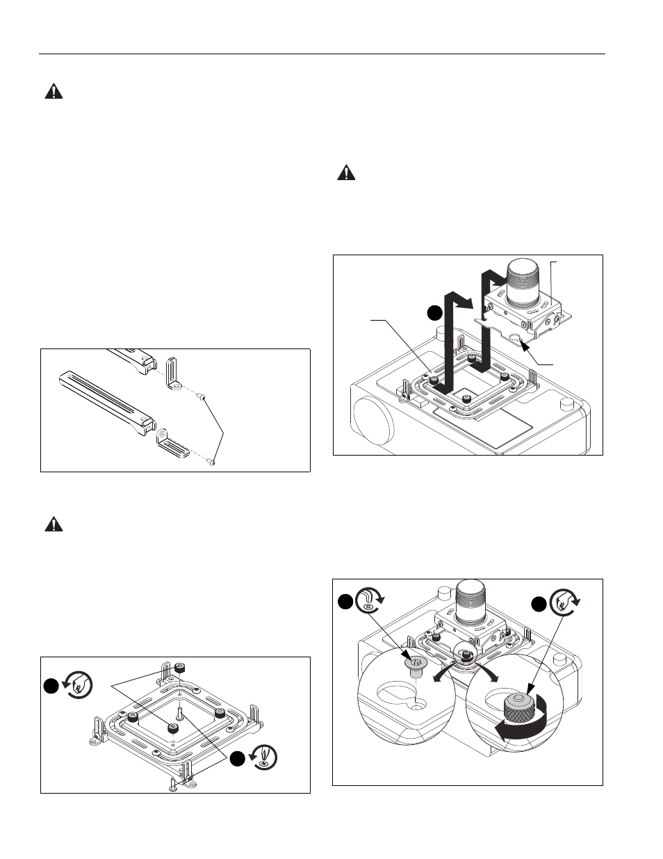
2.
Orient projector attached to universal interface with
projector mount. (See Figure 17)
3.
Lift projector so that screws with thumb nuts are aligned with
mounting slots in projector mount.
4.
Slide projector with universal interface into mounting slots in
projector mount until screws are seated against the back of
mounting slots.
WARNING:
IMPROPER INSTALLATION CAN LEAD TO
PROJECTOR FALLING RESULTING IN SERIOUS
PERSONAL INJURY OR DAMAGE TO EQUIPMENT. Make
certain mounting slots in projector mount slide under thumb
screws and that screws are seated in the back of slots.
Figure 17
5.
Secure projector to mount (See Figure 18) by either:
•
Turning four thumb nuts until tight; or
•
SECURITY ATTACHMENT ONLY:
Tightening two
remaining thumb nuts, and installing two flat head
security screws (F2) into corners where thumb nuts
were previously removed.
Figure 18
Remove foot and
reattach with slot
on bottom
1
x 2
1
x 2
3
Back of
mounting
slot
Front of
projector
Universal
interface
Projector
mount
5
x 4
x 2
5
Security
Attachment
Easy-Release
Attachment