Module internal database, Dnp master database layout, 1 module internal database – ProSoft Technology 5201-DFNT-DNPM User Manual
Page 8: 2 dnp master database layout
DNPM ♦ ProLinx Gateway
Functional Overview
DNP 3.0 Master
Driver Manual
Page 8 of 56
ProSoft Technology, Inc.
September 30, 2009
1.1
Module Internal Database
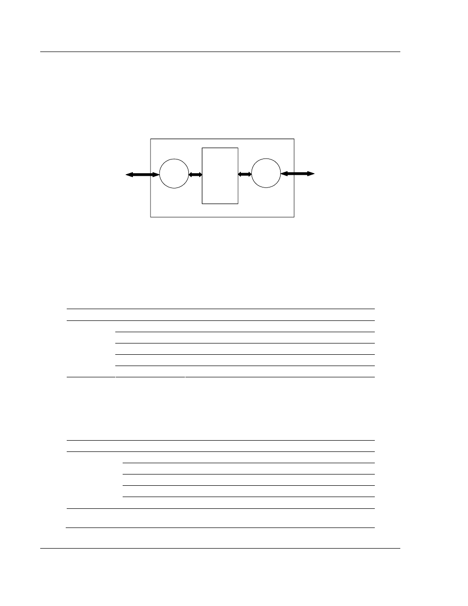
The internal database is central to the functionality of the module. This database
is shared between all the ports on the module and is used as a conduit to pass
information from one device on one network to one or more devices on another
network. This permits data from devices on one communication port/network to
be viewed and controlled by devices on another port/network.
Other
ProLinx
Protocol
Driver
DNPM
Driver
ProLinx
Communication
Gateways
Internal
Database
(Up to 4000 regs )
Other
ProLinx
Protocol
Driver
Driver
ProLinx
Communication
Gateways
Internal
Database
regs )
1.2
DNP Master Database Layout
Central to the functionality of the DNP driver is the database. This database is
used as the interface between remote DNP devices and the other protocol
implemented on a module. The content and structure of the user data area of the
database is completely user defined. The following illustration shows the general
format of the module’s database:
DATA AREA
DATA SIZE
BINARY INPUTS
1 WORD PER 16 POINTS
ANALOG INPUTS
1 WORD PER POINT
COUNTER DATA
2 WORDS PER POINT
BINARY OUTPUTS
1 WORD PER 16 POINTS
DNP DATA
ANALOG OUTPUTS 1 WORD PER POINT
The first word of the module’s database contains the first 16 points of binary input
data (if defined). It is important to understand how the data is mapped to the
database so that it can be accessed by the other protocol. Each DNP data type
has a fixed size. This size is used in conjunction with the number of points
configured for the type to determine the size and location in the database. The
following is an example of a user database with a defined set of point counts:
DATA AREA
REGISTERS
CFG VALUES
BINARY INPUTS
0 TO 1
2
ANALOG INPUTS
2 TO 51
50
COUNTER DATA
52 TO 71
10
BINARY OUTPUTS
72 TO 73
2
DNP DATA
ANALOG OUTPUTS
74 TO 113
40
USER DATA
REMAINING DATA
AREA
114 TO 3999