Display connector pin out, Commands, Demonstration programs – Remote Processing RPC-210 User Manual
Page 51
DISPLAY & KEYPAD PORTS
BASIC
SECTION 11
Page 11-3
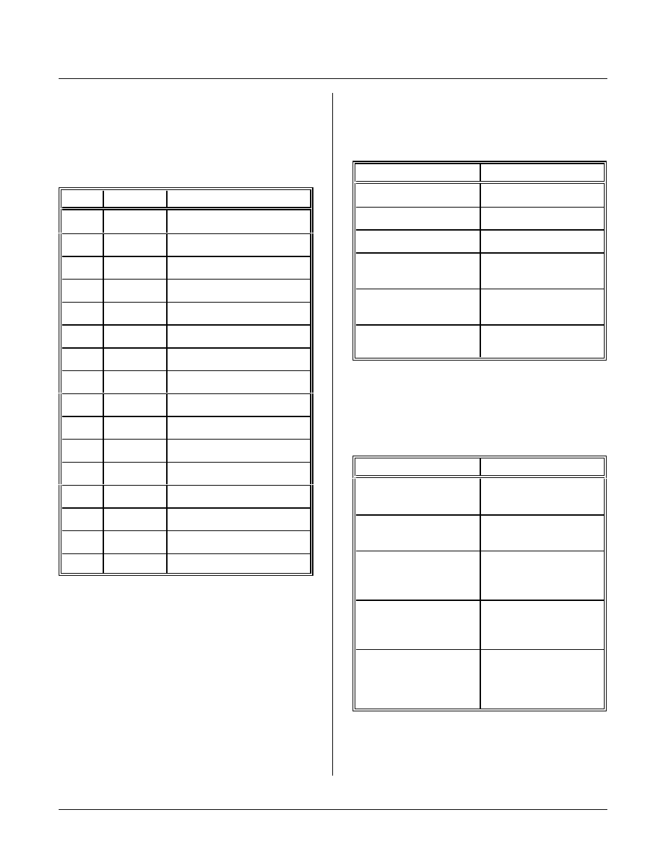
DISPLAY CONNECTOR PIN OUT
The display port uses port A of the 82C55 for data and
control. The table b elow lists a pin nu mber and its
intended function. A display may not use all lines even
though they are available. This is true for the E2 line.
J4 Pin
Port A bit
Function to display
1
2
Data 6
2
3
Data 7
3
0
Data 4
4
1
Data 5
5
N C
No connect
6
N C
No connect
7
N C
No connect
8
N C
No connect
9
5
Read/Write (0 = write)
10
6
Enable signal strobe 1
11
none
Angle/c ontrast adjust
12
4
Register/data select
13
none
+ 5V power
14
none
Ground
15
N C
No connect
16
7
Enable signal strobe 2
LC d isplays oper ate in 4 bit data tr ansfer m ode. Data
lines 0 - 3 on the display are not used.
COMMANDS
The following RPBASIC-52 com mands are used for the
display and keypad.
Command
Function
CLEAR DISPLAY
Clears entire display
C L E A R D IS P L A Y LI N E
Clears line of display
CONFIG DISPLAY
Specifies display type
DISPLAY
Prints string at
row/column specified
KEYPA D(n)
Reads keypad character
or status.
ON KEYPAD
Dire ct subrou tine line to
execute on key pr ess.
DEMONSTRATION PROGRAMS
The following programs may be used to verify proper
operation of a keypad or display. Programs are located
in the BASIC-52 directory.
P r og r am N a m e
Description
KEYPAD1.BAS
Read & process keypad
presses in polled mode.
KEYPAD2.BAS
Process keypad presses
in interrupt mode.
DISP-1.BAS
Display demo for 4 x 20
LC display. Prints tick
time.
DISP-2.BAS
Display demo for 4 x 40
LC d isplay. Prints da te
and time.
DISP-3.BAS
Demo for 4 x 40 LC
display. For mats and
prints analog inputs 0 and
1.