Remote Processing RPC-210 User Manual
Page 48
ANALOG I/O
BASIC
SECTION 10
Page 10-6
Gener ally, y ou have a fe w milli-am ps for you r circ uit.
You may be able to get more than this in your
circumstance.
Unfortuna tely, the only w ay to tell is to try it. The best
way to tell is to connect the devices to the board and load
the ± supplies. M easure the voltages. J10-18 should be
a t l ea st 7. 5 V , i f y o u w i ll us e t he 0 -5 V A / D a n d D / A
range. J10-20 should be about -5V.
An alternative is to put analog I/O in the 2.5V max.
range. Then use the + 5V supply for amplifier supply.
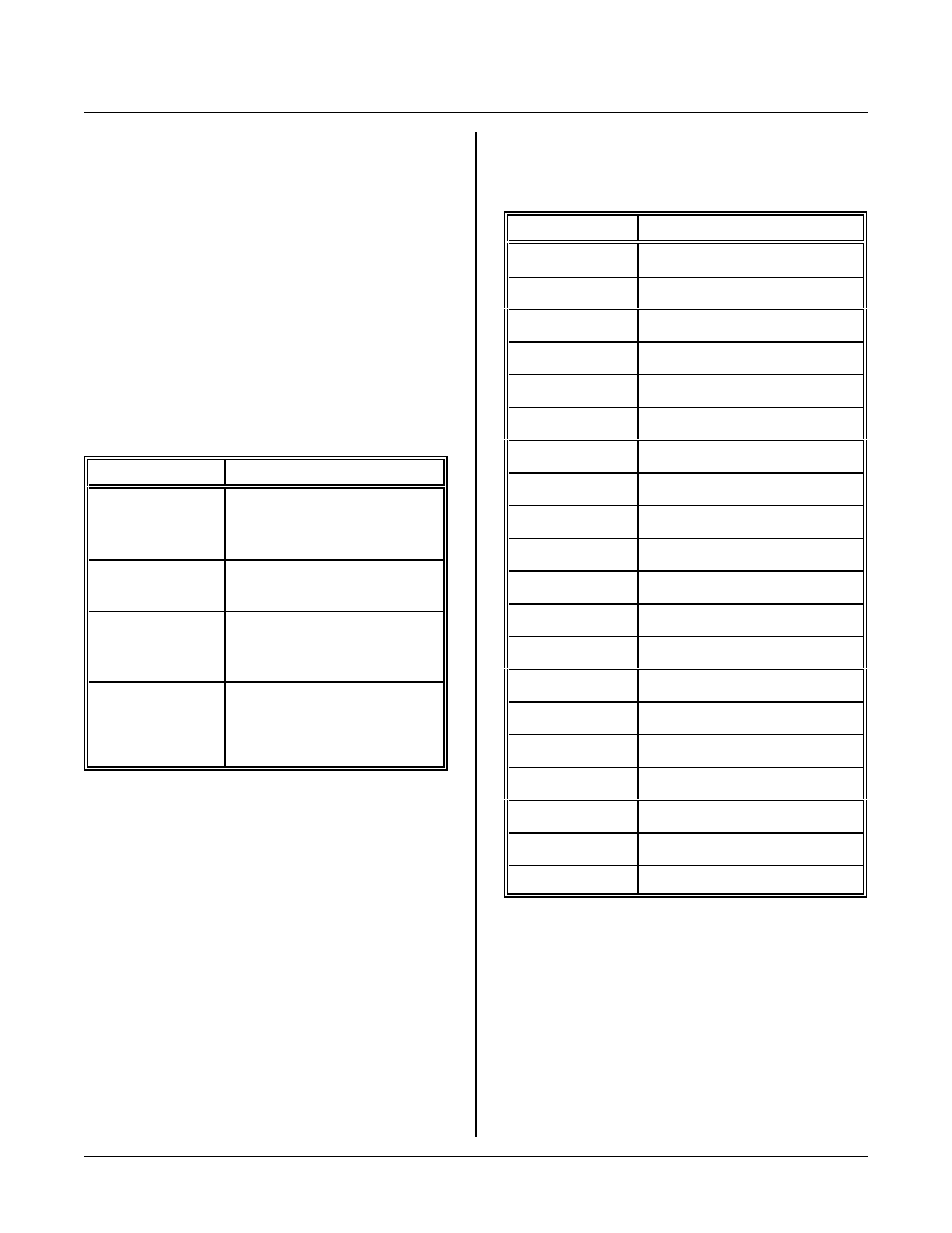
APPLICATION PROGRAMS
Program s are in the BASIC52 directory.
P r og r am N a m e
Description
AIN-1.BAS
All channe ls printed ou t,
including tem peratur e. P rints
out actual voltage at pin.
AIN-2.BAS
P e r fo r m s t im e d A / D
conversions using ON TICK.
AIN-3.BAS
Figures offse t and gain error s.
Stores and retrieves calibration
constants.
210CAL.BAS
Prom pts you to adjust R16 and
calibrate e ach chann el.
Requires an external reference
of 4.900 volts.
J10 ANALOG I/O CONNECTOR PIN OUT
The table below is a pin out for analog connector J10.
J1 Pin
N a m e
1
Analog inp ut 0
2
Ground
3
Analog inp ut 1
4
Ground
5
Analog inp ut 2
6
Ground
7
Analog inp ut 3
8
Ground
9
Analog inp ut 4
10
Ground
11
Analog inp ut 5
12
Ground
13
Analog inp ut 6
14
Ground
15
Analog inp ut 7
16
Ground
17
Analog ou tput 0
18
About + 8V
19
Analog ou tput 1
20
About -8V