Remote Processing RPC-210 User Manual
Page 38
COUNTER/TIMERS
BASIC
SECTION 8
Page 8-1
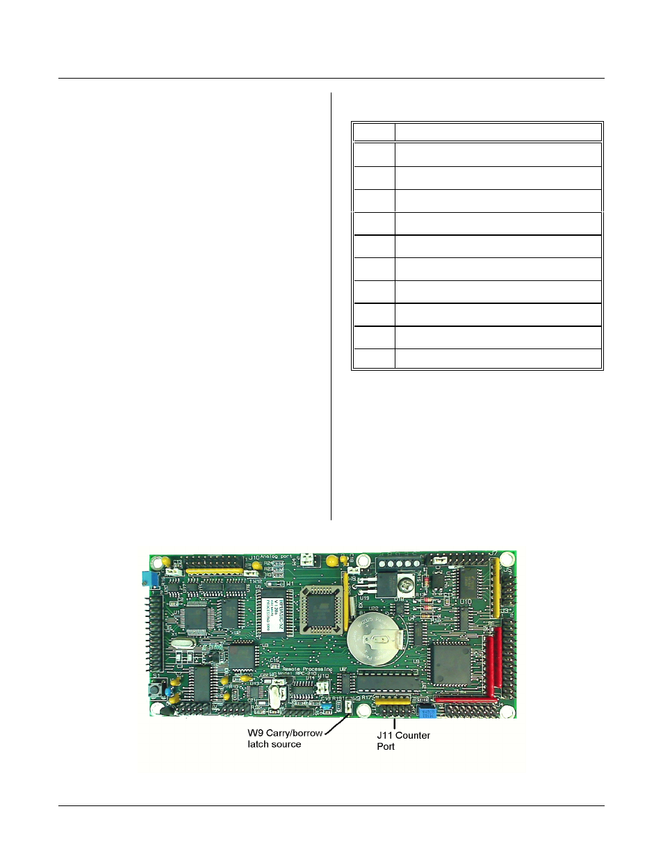
Figure 8-1
INTRODUCTION
COUNTE R/TIMERS
S E C T IO N 8
Ther e is one counte r input and two pulse ou puts
available on the RPC-210. C ounter input consists of
U21 is a counter/quadr ature encoder IC. Its accumulator
is 24 bits wide (about 16 million counts). Maxim um
input frequency is 20 MHZ. The counter is software
program med for a ll of its modes.
If COM1 is not used, a pulse output from the UART
may be used for pulse generation.
The RTC can generate square waves from 2 to 32768
Hz.
These pulses may be used in conjunction with the
counter to measur e a pulse wid th or pr ovide an alter nate
means of m easuring time inter vals between two eve nts.
COUNTER/ENCODER
U21 may be programmed as an up/down or quadrature
encoder counter. A pres et count m ay be loaded to
generate an interrupt (INT 0) when the count goes
through 0 or some other number. Counts may be read
“on the fly” .
J11 CONNECTOR PIN OUT
Pin #
Description
1
Counter ‘B’ input
2
Counter ‘A’ input
3
Load counter (LCTR)
4
High frequency clock source (CO M1)
5
A-B Gate
6
Ground
7
Carr y output
8
I N T 0 ( to C P U )
9
Borrow output
10
Latched carry or borrow output
PULSE OUTPUTS
A pulse output is available to perfor m timing functions.
This pulse is generated from the COM 1 UART (U13).
Since the UART is put into test mode, C OM1 m ay not
be used for serial communication when it is generating
pulses.
Available clock outputs are 16X the baud r ate. T hus,
pulses from 3.6864 MHZ to 9600 are available.