Remote Processing RPC-210 User Manual
Page 29
DIGITAL LINES
BASIC
SECTION 6
Page 6-1
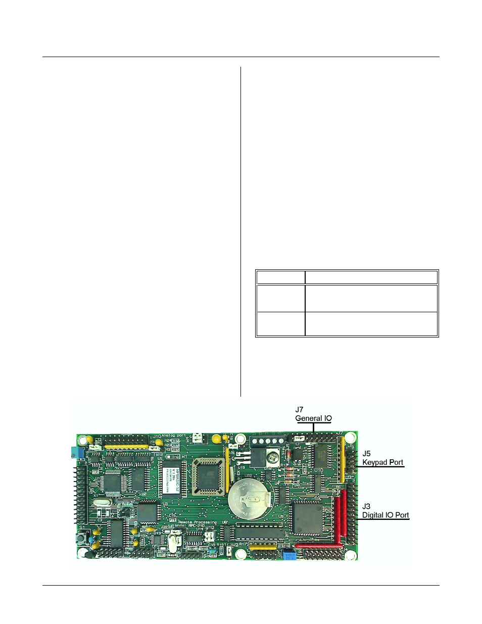
Figure 6-1 Digital Input - Output connectors
INTRODUCTION
DIGITAL LINES
S E C T IO N 6
Digital I/ O lines ar e used to inter face with op to-module
racks, switches, low current LED’s, and other TTL
Digital I/ O lines ar e used to inter face with op to-module
racks, switches, low current LED’s, and other TTL
devices. The RP C-210 has 37 of these lines. 24 go to 26
pin connector J3. The r emaining lines go to J5 and J7.
Some of the lines ma y be used for m ultiple uses. The se
uses include:
LCD display at J4 (shared with J3)
Keypad at J5. Inputs only at J7
Keypad column outputs 1-4 are dedicated to the keypad.
T h is is b ec a us e ke y pa d sc a nn in g au to m a ti c i n R P B AS I C -
52. Howe ver, keypad r ow inputs m ay be used fo r inputs
at J7.
J7-17 is used for autorun detect. When this line is low,
RPBASIC-52 autom atically executes the first BASIC
program on power up, reset, or CALL 0 command.
Three RPBASIC-52 comm ands are used to access lines
at J3: LINE, LINEB, and LINE #. Two event-driven
commands, ON LIN E and ON C OUN T, monitor the
lines. Lines at J3 ar e configur ed for inp uts and outputs
using the CONFIG LINE command. L ines at the other
ports a re ac cessed u sing LI NE B.
RPBASIC-52 Programm ing Manual difference
The synta x for L INE B is slightly differen t than shown in
the RPBA SIC-52 m anual.
A = LIN EB( address)
Read from I/O area
L IN E B, address, data
Write to I/O area
There is no i/o bank param eter as sho wn in the m anual.
The Program ming Manual states that lines are checked
every 5 mSec for ON COUNT and ON LINE. Lines are
checked every 10 mSec on the RP C-210. Maximum
counting frequency is effectively 45 Hz. Lines must be
stable for 10 mSec or longer to ensure detection.
ELECTRICAL CHARACTERISTICS
Digital output ports sink and source a limited amount of
curr ent. Each por t is different a s shown in the table
below:
Ports
Current @ condition
J3
20 mA sink @ 1V (low)
20 mA source @ 3.6V (high)
J5 & J7
10 mA sink @ 1V (low)
10 mA source @ 3.6V (high)
Digital inputs a t J3 have 100K resistor pull ups. Inputs
at J5 and J7 have 10K pull ups. For a m ore noise
immu nity, a dd a lower value pull up r esistor to the inp ut.
NOTE:
The 82C55 inputs at port A are latched.