Remote Processing RPC-210 User Manual
Page 49
DISPLAY & KEYPAD PORTS
BASIC
SECTION 11
Page 11-1
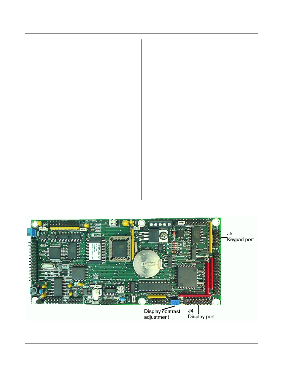
Figure 11-1 Keypad and Display Connectors
INTRODUCTION
DISPLAY PORT
SECT ION 11
Port J4 supports 4 x 20 and 4 x 40 character LC
displays. Eight lines fr om digital I/ O por t J3 are use d to
write to the display. Angle/ contrast a djustment v ia R7 is
provided as are + 5V and ground. Figure 13-1 on the
next page shows the location of the connector and R7.
Eight I/O lines for the display are shared between J3 and
J4. All port A lines are used for the display.
A number of character displays may be used. Program
examp les assume a HD 44780 contr oller is used. This
controller is used on Optrex, AND , Stanley, and other
displays. IEEE LC displays have been successfully used.
Some VF displays from Noritake are LCD interface
compatible.
The keypad port at J5 is for a 4 x 4 matrix, 16 position
keypad. The RPBASIC-52 oper ating systems scans and
debounce s the keypad e very 10 0 mSec. A key is
recogn ized whe n a row and colum n connect.
RPBASIC-52 scans and debounces the keypad every 100
m S e c. K e y pa d pr e ss e s a r e re t ur n e d a s a n u m be r fr o m 1
to 16 using the KEYPAD (0) function. Keypad scanning
is always active and cannot be turned off. Up to 8 key
presses are buffered.
K e yp a d p r e ss e s a r e mu lt i- ta s ke d us in g ON K E Y P A D .
When a key is pressed, the program br anches to the
subroutine.
Keypads from Rem ote Processing simply plug into J5.
Limit keypad cable length to less than 2 meters (6 feet).
CONNECTING DISPLAYS
The display port supplies all control lines for character
LC d isplays. Displays pu rchase d from Remo te
Proc essing include a cable. Simply con nect the 16 pin
connector to J4 and the other end into the display.
WRITING TO THE DISPLAY
The display port m ust be initialized using 2 command s.
First, port A must be configured as an output using
CONF IG LINE 100. Port B and C may be configured
as inputs or outputs as necessary. When setting the
output status, port A should be set to 255. The
following example sets ports A and B to output and port
C to input.
CONFIG LINE 100,5,255,255,255