Connections & wiring diagrams, Figure 3. connections with loop-powered backlight – Precision Digital PD6800 User Manual
Page 13
PD6800-0L1 Loop-Powered Process Meter
Instruction Manual
13
Connections & Wiring Diagrams
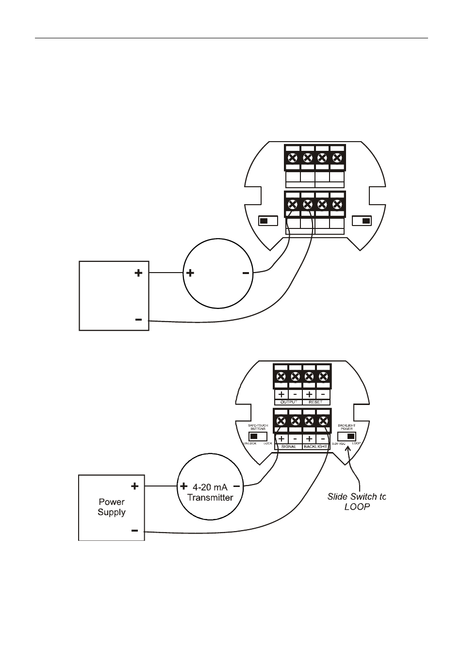
Signal connections are made to a four-terminal connector mounted in the base of the
enclosure. The enclosure also provides one internal and one external earth
grounding screw. For installations without backlight, only the two signal terminals are
connected. The 4-20 mA input with no backlight has a maximum voltage drop of 3 V
and is wired as shown in Figure 2. The loop-powered backlight configuration requires
a total maximum voltage drop of 6 V. The backlight is recommended for dim lighting
conditions and is enabled when wired as shown in Figure 3 or Figure 4.
Figure 2. Connections without Backlight
Figure 3. Connections with Loop-Powered Backlight
4-20 mA
Transmitter
Power
Supply
SAFE-TOUCH
BUTTONS
BACKLIGHT
POWER
UNLOCK
LOCK
LOOP
9-36 VDC
+ - + -
SIGNAL
BACKLIGHT
+ - + -
OUTPUT
RESET