Multi-Contact MA255 User Manual
Page 7
Advanced Contact Technology
www.multi-contact.com
7 / 12
12
13
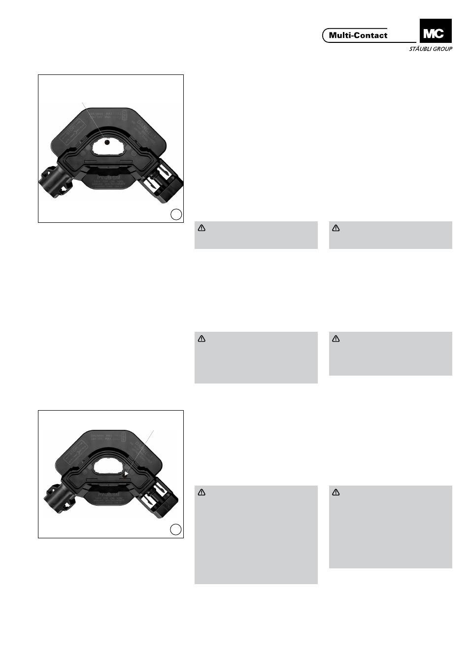
(ill. 12)
Después de orientar correctamente y
adherir la caja de conexión a la parte
posteior del módulo PV, introduzca a
través de la abertura en PV-JB/SM un
termodo diseñado especialmente en
el extremo de un soldador de reflujo
(barra caliente) o un soldador de hierro
con una punta de 4 mm de diámetro y
suelde las dos solapas de soldadura a
las cintas del bus utilizando la presión,
temperatura y tiempo apropriados.
Para una correta soldadura y adhe-
rencia de los ribbons de soldaura al
embarrado, se requiere preestañar al
embarrado (un chapado de soldadu-
ra de plata a la barra es suficiente) y
aplicar un flujo (no limpio).
(ill. 12)
After properly orienting and bonding
the junction box to the back of the PV
module, reach through the opening in
PV-JB/SM with a specially designed
thermode on the end of a reflow sol-
dering (Hot Bar) machine or
Ø 4 mm soldering iron tip and solder
both solder flaps to the bus ribbons
using the appropriate pressure, time,
and temperature. For proper solder-
ing and adhesion of the solder tabs to
the busbar it is required to pre-tin the
busbar, (silver solder plating on the
busbar is sufficient), and apply a (no
clean) flux.
Precaución
No se recomienda usar con rib-
bons de aluminio
Caution
Use with an aluminium bus rib-
bon is not recommended.
Después de finalizar la operación de
soldadura, elimine el calor y mantenga
la presión hasta que la zona de sola-
dura haya solidificado.
El método de conexión de soldadura
debe ser evaluado de acuerdo con la
norma IPC J-STD-001D o equivalente.
After the soldering operation is
complete, remove heat and maintain
pressure until the solder area has
solidified.
The solder connection method should
be evaluated according to the stand-
ard IPC J-STD-001D or equivalent.
Nota
Tenga especial cuidado de no
entrar en contacto con ninguno
de los componentes de plástico
durante la operación de solda-
dura.
Attention
Take special care not to come in
contact with any plastic com-
ponents during the soldering
operation�
Sellado de la caja de
conexión
Potting of the junction box
(ill. 13)
Llene la caja de conexión con material
encapsulante hasta la parte superior
de la abertura en la PV-JB/SM a fin de
que una pequeña cantidad de encap-
sulante (aprox. 1 cc) se derrame en el
orificio de desbordamiento.
(ill. 13)
Fill the junction box with potting
material to the top of the opening in
the PV-JB/SM so that a small amount
of pottant (approx. 1 cc) spills in to the
overflow well.
Precaución
NO vierta abruptamente para
evitar la formación de bolsas de
aire en el encapsulante o para no
atrapar el aire dentro de la caja de
conexión. En el caso de rellenar
manualmente, se recomienda
llenar la caja de conexión a los
2/3, dejar que las burbujas de
aire suban a la superficie durante
aprox. 10 segundos y luego llenar
el volumen restante.
Caution
DO NOT pour abruptly as to crea-
te air pockets in the pottant or to
trap any air inside of the junction
box.
It is recommended if dispensing
manually to fill the junction box
2/3 full, let air bubbles surface for
approx. 10 seconds, then fill the
remaining volume.
Abertura en PV-JB/SM
Opening in PV-JB/SM
Orificio de desbordamiento
Overflow well