Multi-Contact MA203 User Manual
Page 2
ill.2
ill.3
Kabelverschraubung
Cable gland
Presse-étoupe
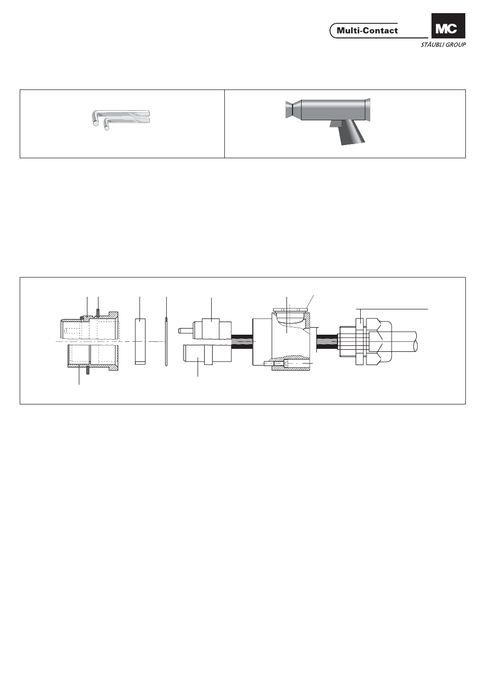
1
3
2
6
7
8
9
5
4
ill.1
2/6
(ill.2)
Heissluftgebläse 2500 W
(nur für Gehäuse Gr. 3)
(ill.2)
Hot air blower 2500 W
(Only for housings size 3).
(ill.2)
Générateur d'air chaud 2500 W
(Uniquement pour boîtier Gr. 3)
(ill.3)
Konfektionierter Kontaktträger (6 bzw.
7) in Gehäusevorderteil (1 bzw. 2) ein-
setzen, dabei auf Führungsnut achten.
Gehäuserückteil (8) und O-Ring (5) mit
Imbusschrauben auf Gehäusevorder-
teil (1 bzw. 2) schrauben. Zwischenring
(4) nur bei Stiftgehäuse Gr. 3 einsetzen.
Kabelverschraubung anbringen. Freie
Kabelverschraubung-Öffnung im Ge-
häuserückteil (8) mit Verschlussschrau-
be (9) schliessen.
(ill.3)
Introduire le support confectionné dans
le boîtier (6 ou 7) avant (1 ou 2), en veil-
lant au bon positionnement du détrom-
page. Visser le boîtier arrière (8) avec le
joint torique (5) sur le boîtier avant (1 ou
2) en utilisant les vis correspondantes.
Pour le boîtier mâle de taille 3 (Gr.3), met-
tre l'entretoise (4) en place.
Ramener le presse-étoupe et le serrer.
Fermer l’ouverture du boîtier arrière (8)
(ill.3)
Insert the fully assembled contact car-
rier (6 or 7) in the front section of the
housing (1 or 2), observing position of
alignement groove. Install O-Ring (5)
and screw housing back section (8) to
front section (1 or 2) with all screws; on-
ly in the case of size 3 pin housing, it is
also necessary to install spacer ring (4).
Attach the cable gland. Close off the un-
used cable gland tapped hole in the hou-
sing back section (8) with a closure
screw (9).
Montage der Steckverbinder
Assembly of connector
Assemblage du connecteur
Notwendiges Werkzeug
Tools required
Outillage nécessaire
(ill.1)
Sechskantschlüssel
SW3 + SW4.
(ill.1)
Hex. key wrench
A/F3 + A/F4.
(ill.1)
Clй а 6 pans 3 mm et 4 mm.
1 = Stift-Gehäusevorderteil
2 = Buchsen-Gehäusevorderteil
3 = Sicherungsring
4 = Zwischenring
5 = O-Ring
6 = Stiftkontaktträger bestückt
7 = Buchsenkontaktträger bestückt
8 = Gehäuserückteil
9 = Verschlussschraube
1 = Pin housing front section
2 = Socket housing front section
3 = Retaining ring
4 = Spacer ring
5 = O-Ring
6 = Assembled pin carrier
7 = Assembled socket carrier
8 = Housing back section
9 = Closure screw
1 = Boîtier avant (
2 = Boîtier avant (
broche)
douille)
3 = Circlip
4 = Entretoise
5 = Joint torique
6 = Support broche confectionné
7 = Support douille confectionné
8 = Boîtier arrière
9 = Vis d'obturation
www.multi-contact.com
Advanced Contact Technology