Sealey TA304 User Manual
Page 5
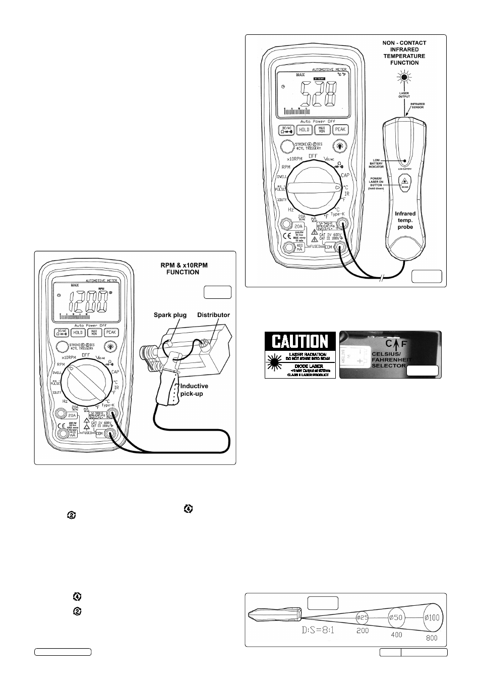
5.12. RPM and ×10RPM
5.12.1. using the rotary switch, select either the
RPM range or the ×10RPM
range (1,000 to 12,000 rPM) and multiply the displayed reading by ten
to get actual rPM.
5.12.2. Press stroKE / DIs button to select through rPM for 4-stroke,
rPM for 2-stroke and DIs ignitions.
5.12.3. connect the inductive pickup leads to the meter.
5.12.4. Insert the black lead into the
COM terminal.
5.12.5. Insert the red lead into the
V-Ω-RPM terminal.
5.12.6. open the inductive pickup and place it onto a spark plug wire. If no
reading is received, unhook the clamp, turn it over and connect again.
NOTES:
5.12.7. Position the inductive pick-up as far away from the distributor and the
exhaust manifold as possible.
5.12.8. Position the inductive pick-up to within six inches of the spark plug or
move it to another plug wire if no reading or an erratic reading is
received.
5.12.9.
RPM 4 : for rPM of 4-stroke engines which have 1 ignition on
every 4 engine strokes
5.12.10
RPM 2 : for rPM of DIs ( Distributorless lgnition system) &
2-stroke engines which Have 1 ignition on every 2 engine strokes
PLEASE NOTE - THE RPM PICK-UP HAS AN ADJUSTABLE
SENSITIVITY SWITCH THAT CAN ALSO BE USED TO CORRECT AN
UNSTABLE READING.
5.11. ms-PULSE (Pulse Width) & ms- PERIOD (Period)
5.11.1. Pulse Width is the length of time an actuator is energized. for example,
fuel injectors are activated by an electronic pulse from the Engine
control Module (EcM). this pulse generates a magnetic field that pulls
the injector nozzle valve open. the pulse ends and the injector nozzle
is closed. this open to close time is the Pulse Width and is measured in
milliseconds (ms). the most common automotive application for
measuring pulse width is on fuel injectors. You can also measure the
pulse width of the fuel mixture control solenoid and the idle air control
motor.
This exercise shows how to measure Pulse Width (mS) on Port
Fuel injectors.
5.11.2. select the “ms-Pulse” function with the rotary switch .
5.11.3. Press the trigger± button for 2 seconds until the negative (-) trigger
slope is displayed on the upper left side of the display.
Note: the applied time for most fuel injectors is displayed on the negative (-)
slope.
5.11.4. Insert the black lead into the
COM terminal.
5.11.5. Insert the red lead into the
V-Ω-RPM terminal.
5.11.6. connect jumper wires between the fuel injector and the harness
connector.
5.11.7. touch the Black test probe to a good ground at the fuel injector or the
negative (-) vehicle battery post.
5.11.8. touch the red test probe to the fuel injector solenoid driver input on the
jumper cable.
5.11.9. start the engine. A pulse width in milliseconds should be read.
Note: Initially, the unit will read “OL”, then readings will descend and
stabilize to the actual pulse.width. If “OL” remains, re-check your
connections.
5.13. Infrared Temperature Probe Introduction
LASER SAFETY
Use extreme caution when the laser beam is turned on.
DO NOT let the beam enter your eye, another person’s eye or the
eye of an animal.
DO NOT let the beam strike your eye from a reflective surface.
5.13.1. the Infrared temperature Probe is a non-contact temperature
measurement accessory for use with a test instrument capable of
measuring
Dc volts in the millivolt range (200mv/400mv/600mv/2v/4v/6v
range) . the probe has a temperature range of -30°c to 550°c (-22°f to
1022°f), with a basic accuracy of 2% of reading, and an output of 1 mv
Dc per °c or °f. temperature is measured by pointing the probe at the
surface to be measured, and reading the temperature on the test
instrument display. celsius or fahrenheit is selected by moving the
selector situated in the battery box (see fig.11).
5.13.2.
Compatibility
the probe is compatible with the automotive meter's Infrared
temperature (°c or °f) ranges that have a minimum of 1 MΩ input
impedance and accept safety shrouded, standard diameter 0.16 in.
(4 mm) banana plugs.
5.13.3.
Field of View
the meter’s field of view is 8:1, meaning that if the meter is 8 inches
from the target, the diameter of the object under test must be at least 1
inch. other distances are shown below in the field of view diagram.
refer to the chart printed on the meter for more information. Make sure
that the target is larger than the unit’s spot size. the smaller the target,
the closer you should be to it. When accuracy is critical, make sure the
target is at least twice as large as the spot size.
5.13.4.
Operation
to take a measurement, perform the following steps:
5.13.5. Insert the black lead into the
COM terminal and the red lead into the
V-Ω-RPM terminal.
5.13.6. select Infrared temperature (°c-Ir-°f) on the test instrument.
5.13.7. Press and hold down the probe laser button to turn on the laser.
5.13.8. Point the tip of the probe as close as possible to the object being
measured without touching the object.
5.13.9. read the test instrument display.
fig.9
fig.10
fig.12
fig.11
tA304 Issue:4(I) - 17/06/14
Original Language Version
© Jack sealey Limited