Fig.3 fig.4, Push button functions 5. meter functions – Sealey TA304 User Manual
Page 3
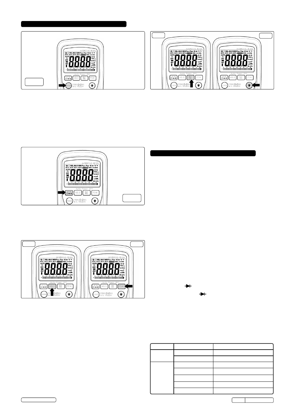
4.3. DATA hOLD (fig.5a)
the Data Hold function allows the meter to "freeze" a measurement for
later reference.
4.3.1. Press the DAtA HoLD button to “freeze” the reading on the display.
the “HoLD” symbol will appear in the display.
4.3.2. Press the DAtA HoLD button again to return to normal operation.
4.4. PEAK hOLD (fig.5b)
the Peak Hold function captures the peak Ac or Dc voltage or current.
the meter can capture negative or positive peaks as fast as
1 millisecond in duration.
4.4.1. turn the function switch to the A or V position.
4.4.2. Press and Hold the PEAK button until “cAL” appears in the display. this
procedure will zero the range selected & return the meter to manual
ranging.
4.4.3. Press the PEAK button, Pmax will display.
4.4.4. the display will update each time a higher positive peak occurs.
4.4.5. Press the PEAK button again, Pmin will display. the display will now
update and indicate the lowest negative peak.
4.4.6. to return to normal operation, press and hold the PEAK button until the
Pmin or Pmax indicator switches off. note: If the function switch
position is changed after a calibration the Peak Hold calibration must be
repeated for the new function selected.
4.5. MAX/MIN BUTTON (fig.6a)
4.5.1. Press the MAX/MIn button to activate the MAX/MIn recording mode.
the display icon "MAX or MIn" will appear. the meter will go to
manual ranging & display and hold the maximum or minimum reading
and will update only when a new “max or min” occurs.
4.5.2. Press the MAX/MIn key and a blinking “MAX MIn” will appear. the
meter will display the present reading, but will continue to update and
store the max and min readings.
to exit MAX/MIn mode press and hold the MAX/MIn key for 2 seconds.
4.6. BACKLIGhT BUTTON (fig.6b)
4.6.1. Press the BAcKLIGHt button to turn the backlighting on.
4.6.2. Press the BAcKLIGHt button again to turn the backlighting off.
fig.5a
fig.5b
fig.6a
fig.6b
4. PUSh BUTTON FUNCTIONS
5. METER FUNCTIONS
4.2. MODE BUTTON
Press the mode pushbutton to select the following functions;
DC/AC Voltage, DC/AC Current Resistance, Diode, Continuity &
Capacitance
4.1. MANUAL RANGE & Stroke 4/2(DIS),
hz, %, ms +, CYL Button
Press to this button to select;
STROKE 4, 2DIS, Hz ,%, ms+, CYL range & V/A/ Resistance manual
Range
4.1.1.
MANUAL RANGING
the meter turns on in the autoranging mode. Press the range button to
go to manual ranging. the display icon " " will appear. Each press of
the range button will step to the next range as indicated by the units and
decimal point location. Press and hold the range button for two seconds
to return to autoranging.
fig.3
fig.4
5.1. VOLTAGE (V)
5.1.1. select the
Volts “ V” range with the rotary switch.
5.1.2. the meter will automatically select the best voltage (V) range.
5.1.3. select DcV or AcV with the
MODE button.
5.1.4. Insert Black lead in
COM terminal.
5.1.5. Insert red lead in
V-Ω-RPM terminal
5.1.6. touch the Black probe to ground or to the negative (-) circuit
5.1.7. touch the red probe to the circuit coming from the power source
IMPORTANT: Voltage must be measured in parallel (Red probe
measuring circuit from power source).
WARNING: When measuring voltage, be sure the Red test lead is in
the terminal marked “V”. If the test lead is in an Amp (A) or
Milliampere (mA) terminal, you may be injured or the meter damaged.
5.2. RESISTANCE (Ω)
IMPORTANT: If you are testing an application that has capacitors in the
circuit, be sure to turn the power off on the test circuit and discharge all
capacitors. Accurate measurement is not possible if external or residual
voltage is present.
5.2.1. select the
Resistance “ Ω” range with the rotary switch.
5.2.2. select the
Resistance “Ω” function with the Mode button. Please note, the
unit defaults to resistance.
5.2.3. Insert Black lead in
COM terminal.
5.2.4. Insert red lead in
V-Ω-RPM terminal
5.2.5. touch the test lead probes across the resistor to be tested.
5.3. Diode Check ( )
IMPORTANT: Turn the power OFF to the test circuit
5.3.1. select the Diode check " " function with the rotary switch and
mode button.
5.3.2. Insert Black lead in
COM terminal.
5.3.3. Insert red lead in
V-Ω-RPM terminal
5.3.4. touch the Black test probe to the negative (-) side of the diode.
5.3.5. touch the red test probe to the positive (+) side of the diode.
5.3.6. reverse the probes: Black to the positive (+) side and red to the negative
(-) side.
Note: A “good” diode will read low in one `direction and high in the other direction
when the probes are reversed (or vice versa).
A defective diode will have the same reading in both directions or read
between 1.0 to 3.0 V. in both directions
DIODE
(- to +)
Reverse probes (+ to -)
GooD
0.4 to 0.9V
over Limit (oL)
over Limit (oL)
0.4 to 0.9V
BAD
over Limit (oL)
1.0 to 3.0V
1.0 to 3.0V
over Limit (oL)
0.4 to 0.9V
0.4 to 0.9V
over Limit (oL)
over Limit (oL)
0.000V
0.000V
tA304 Issue:4(I) - 17/06/14
Original Language Version
© Jack sealey Limited