Fig.7 fig.8 – Sealey TA304 User Manual
Page 4
5.4. CAPACITANCE (CAP)
IMPORTANT: Turn the power OFF to the test circuit
5.4.1. select the capacitance
“ CAP “ function with the rotary switch and
mode button.
5.4.2. Insert Black lead in
COM terminal.
5.4.3. Insert red lead in
V-Ω-RPM terminal.
CAUTION: When checking in-circuit capacitance, be sure that the
circuit has all power removed and all capacitors are fully discharged.
5.4.4. touch the test lead probes across the capacitance circuit to be tested.
5.4.5. read the measured value from the LcD display.
Note: (a) the bar graph is disabled in capacitance measurement mode.
However, since the measurement time of 4mf and 40mf modes is quite
long (3.75s and 7.5s respectively, to be precise,) the bar graph is used
to display the time rest to accomplish the measurement.
(b) In order to obtain an accurate reading, a capacitor must be
discharged before measurement begins. the meter has a built-in
discharge mode to automatically discharge the capacitor. In discharge
mode, the LcD displays “DIs.c”
(c) Discharging through the chip is quite slow. We recommend the user
to discharge the capacitor with some other apparatus.
5.5. AUDIBLE CONTINUITY ( )
IMPORTANT: Turn the power OFF on the test circuit
5.5.1. select the Audible continuity " " function with the rotary switch and
mode button.
5.5.2. Insert Black lead in
COM terminal.
5.5.3. Insert red lead in
V-Ω-RPM terminal.
5.5.4. connect one test probe to each end of the circuit to be tested.
5.5.5. If the circuit is complete, the meter will beep continuously.
5.5.6. If the circuit is open, there is no beep and the display shows oL (over
limit).
5.6. AC or DC Current (A)
IMPORTANT: All current measured flows through the meter.
It is important that you do not:
(A)
Measure current greater than 600 Volts AC or DC, with respect to
ground.
(B)
Do Not Exceed 30 seconds when measuring continuous current
between 1A-20A. Allow five minutes for cool down before continuing.
5.6.1. select the “20A” or “mA” range with the rotary switch.
5.6.2. Press the Mode button to select Ac or Dc.
5.6.3. Insert the black lead into the coM terminal.
5.6.4. Insert the red lead into the 20A or mA terminal (select 20A if you are
unsure of the current draw).
IMPORTANT: Turn OFF all power to the circuit or disconnect the
circuit from the power source.
5.6.5. connect the red probe to the side of the circuit closest to the power
source.
5.6.6. connect the Black probe to the side of the circuit to ground.
5.6.7. turn the power on and test.
Note: Current must always be measured with the meter test probes
connected in series, as described.
5.7. Temperature (ºC/ºF)
IMPORTANT: To avoid heat damage to the meter, keep it away from
sources of very high temperature. The life of the Temperature
Probe is also reduced when subjected to very high temperatures.
Probe operating range is –58º to 482 ºF.
5.7.1. select the temperature
ºC or ºF function with the rotary switch.
5.7.2. Insert the temperature probe connector into the K-type thermocouple
adapter. Insert the adapter into the front of the meter with the negative
pin in the coM terminal socket. touch the end of the temperature
sensor to the area or surface of the object to be measured.
5.8. Frequency(hz)
5.8.1. select the “
hz” frequency function with the rotary switch.
5.8.2. Insert the black lead into the
COM terminal.
5.8.3. Insert the red lead into the
V-Ω-RPM terminal.
5.8.4. connect the Black test probe to ground.
5.8.5. connect the red test probe to the “signal out” wire of the sensor to be
tested.
5.9. Dwell angle ( )
5.9.1. select the “DWELL” function with the rotary switch.
5.9.2. Insert the Black lead into the coM terminal.
5.9.3. Insert the Red lead in V-Ω-RPM terminal.
5.9.4. connect the Black test probe to ground.
5.9.5. connect the red test probe to the wire that connects to the breaker
points (see illustration).
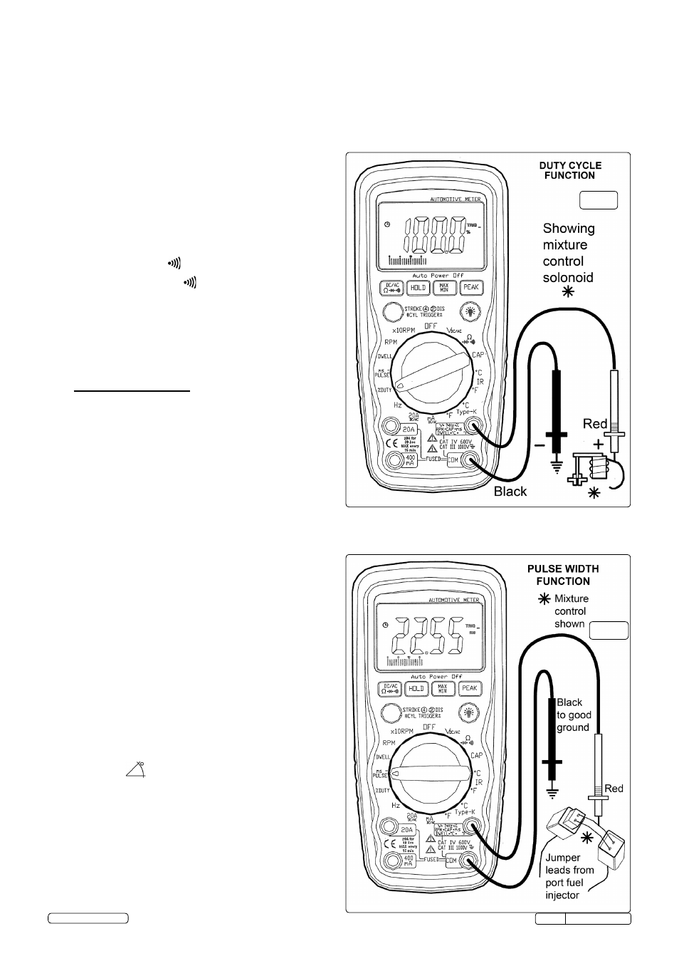
5.10 Duty Cycle (%)
5.10.1 select the “% Duty cycle” function with the rotary switch.
5.10.2 Insert the black lead into the
COM terminal.
5.10.3 Insert the red lead into the
V-Ω-RPM terminal.
5.10.4 connect the Black test probe to ground.
5.10.5 connect the red test probe to the signal wire circuit.
the illustration for a mixture control solenoid is shown with the metering rod in
the closed position. the meter will display the percentage of time the plunger is
in the closed position during one duty cycle.
fig.7
fig.8
tA304 Issue:4(I) - 17/06/14
Original Language Version
© Jack sealey Limited