Fig.2 fig.3 fig.4 – Sealey PP7 User Manual
Page 4
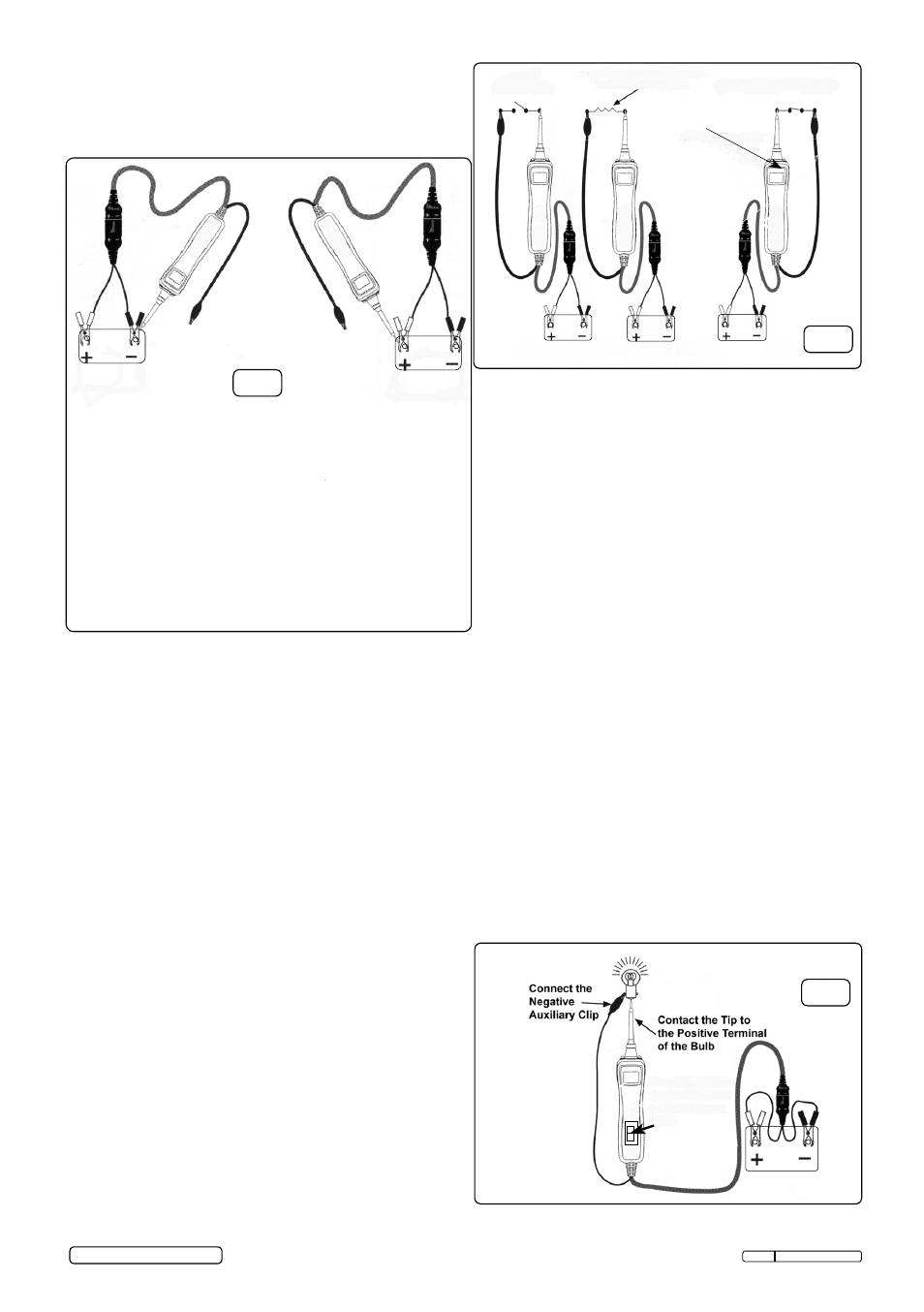
indicator should light GrEEn indicating continuity
through the component.
3.7.3 observe the green LED indicator and quickly
depress and release the switch forward (+). if the
green LED indicator went out and the red positive
sign (+) came on, you may proceed with further
activation.
3.7.4 if the green LED indicator went off at that instant
or if the circuit breaker tripped (LcD display
“c B”), the probe has been overloaded. this
could happen for the following reasons:
• The contact you are probing is a direct earth or
negative voltage.
• The component you are testing is short-
circuited.
• The component is a very high current
component (i.e., starter motor).
3.8
testing trailer lights and connections. see
fig.5.
3.8.1 connect the Probe to a good battery.
3.8.2 clip the auxiliary earth clip to the trailer earth.
3.8.3 Probe the contacts at the jack and then apply
voltage to them. this lets you check the
function.
While the PP7 is in “Power
Mode”, contact the probe
tip to a nEGAtiVE circuit.
the green negative sign (-)
LED will light. if the audio
feature is turned on, a low
pitched tone will sound.
While the PP7 is in “Power
Mode”, contact the probe
tip to a PositiVE circuit.
the red positive sign (+)
LED will light and the
voltage reading of the
circuit will be indicated on
the LcD display. if the
audio feature is turned on,
a high pitched tone will
sound.
3.6 Continuity Testing. See fig.3.
3.6.1 While the probe is in “Power Mode”,
continuity can be tested on wires and components
attached or disconnected from the vehicle’s
electrical system and by utilizing the Probe
tipwhen connected with a chassis earth or the
auxiliary earth lead.
3.6.2 the Probe indicates continuity using two
resistance levels. When the Probe tip has a
resistance to earth of less than 20K ohms but
greater than 2K ohms the LcD will indicate “0.0”
volts but no green (-) LED.
3.6.3 When the resistance to earth is less than 2K
ohms the LcD will indicate “0.0” volts and the
green (-) LED will illuminate.
3.6.4 the higher resistance continuity function is useful
for checking spark plug wires, disconnected from
ignition, solenoids and magnetic pickup coils
3.6.5 the lower resistance continuity for testing relay
coils and wiring.
3.6.6 Another way to check for continuity of
connections to earth or the battery is to use the
power switch. if the circuit breaker trips (LcD
display “c B”) it is clear that there is a good, solid,
low-resistance connection.
3.7 Activating Components in Your Hand. See fig.4
3.7.1 While the Probe is in “Power Mode” components
can be activated in your hand. connect the
negative auxiliary clip to the negative terminal or
earth side of the component being tested.
3.7.2 contact the probe to the positive terminal of the
component, the green negative sign (-) LED
Original Language Version
fig.2
fig.3
fig.4
Press
(+)
to
illuminate
bulb.
no continuity
Continuity <20kΏ but>2kΏ
Continuity<2kΏ
О
Green LED=continuity
© Jack sealey Limited
PP7 issue: 1 - 19/11/12
+
-