Sealey PP7 User Manual
Page 3
2.5 Mode 5 - Peak to Peak threshold setting Mode.
2.5.1 threshold Level setting for the Peak to Peak
Detection in “Power Mode” (
Mode 1).
2.5.2 to set the threshold level for the peak to peak
detection in “Power Mode”, press and hold the
mode switch for one second until you hear a
beep.
2.5.3 You can now toggle the threshold level by a quick
tap of the mode switch and observing the voltage
level settings.
2.5.4 the peak to peak threshold voltage settings loop
incrementally from 0.2, to 0.5, to 1.0, to 2.0, to
5.0, to 10.0, to 50.0 and return back to 0.2 again.
2.5.5 once you select the desired threshold voltage,
press and hold the mode switch again until it
beeps. this returns you to the “Power Mode”
(
Mode 1). You will know that you are in the
“Power Mode” when the LcD display is blank
and/or with the “speaker symbol” shown in
the bottom right corner.
2.6 Polarity indicator and audio tone.
2.6.1 the “rED/GrEEn Polarity indicator” lights up
when the probe tip voltage matches the battery
voltage within ± 0.5 volts. this means that if you
contact a circuit that is not a good earth or a
good positive, you will not see the “rED/GrEEn
Polarity indicator” lighting.
2.6.2 the Audio tone runs parallel to the “rED/GrEEn
Polarity indicator, and will also not react when
contacting a circuit that does not match the
battery voltage within ± 0.5 volts.
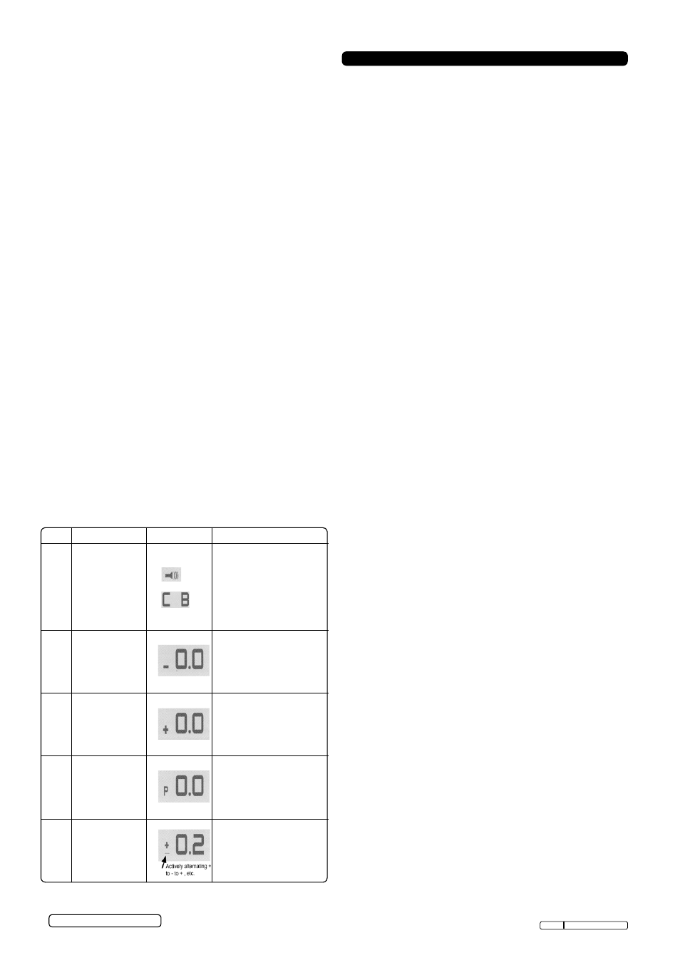
2.7 Mode chart.
3.1 Basic connections.
3.1.1 unroll the Probe cable. connect the rED battery
clip to the PositiVE terminal of the vehicle’s
battery. connect the BLAcK battery clip to the
nEGAtiVE terminal of the vehicle’s battery.
3.1.2 When the probe is first connected to the battery,
it will sound a quick high beep, then a low beep
and then go into “Power Mode”
(see
Mode 1).
3.1.3 the two LED work lights will be on to illuminate
the test area of the probe.
3.2 Quick self test.
3.2.1 Press switch toward (+) to activate the probe with
a PositiVE (+) voltage. the PositiVE sign (+)
LED should light red and the LcD display will
read the battery (supply) voltage. if the tone
feature is turned on, a high pitched tone will
sound.
3.2.2 Press the switch toward (-) to activate the probe
with a nEGAtiVE (-) voltage. the nEGAtiVE
sign (-) LED should light green and the LcD
display will read “0.0”. if the tone feature is turned
on, a low-pitched tone will sound.
3.2.3 the probe is now ready to use.
3.3 audio tone on/off.
3.3.1 Quickly press the mode switch and release
immediately.
3.3.2 if a short high beep is heard, the audio tone is
turned on; if a short low beep is heard, the audio
tone is turned off.
3.4 circuit Breaker.
3.4.1 in “Power Mode” (
Mode 1) with the circuit
breaker tripped, the LcD will display the symbol
“c B”. All other functions of the probe are still
active, so the circuit can still be probed and the
voltage reading observed.
3.4.2 When the circuit breaker is tripped, the probe will
not be able to conduct battery current to the tip
even when the power switch is pressed.
3.4.3 intentionally tripping the breaker and using the
auto probe to probe is an added precaution
against accidentally pressing the power switch.
3.5 Voltage and Polarity Testing. See fig.2.
3.5.1 While the PP7 is in “Power Mode”, contact
the probe tip to a PositiVE circuit. the red
positive sign, (+) LED will light and the voltmeter
will display the voltage.
3.5.2 if the audio feature is turned on, a high-pitched
tone will sound.
3.5.3 While the PP7 is in “Power Mode”, contact
the probe tip to a nEGAtiVE circuit. the green
negative sign, (-) LED will light and the voltmeter
will display the voltage.
3.5.4 if the audio feature is turned on, a low
pitched tone will sound. if neither of the LED
indicators light, the power Probe tip has made
contact to an oPEn circuit. if the audio feature is
turned on, there will be no sound.
3. oPeration
Original Language Version
Mode
navigation
display
output
1
Automatically
selected when
connected to
power source.
• Blank
• W/audio
• C B
• C B w/audio
Displays the average
D.c voltage.
Displays the peak to
peak A.c voltage when
voltage is greater than
Mode 5 threshold setting.
Limited to 65V.
2
Press and hold
Mode switch
until a low
pitched beep is
heard.
captures the most
negative voltage
recorded.
3
Press and hold
Mode switch
until a high to
high pitched
beep is heard.
captures the most posi-
tive voltage recorded.
4
Press and hold
Mode switch
until a low to
high pitched
beep is heard.
Displays the difference
between peak to peak
voltage.
5
Press and hold
Mode switch
until a mid
pitched beep is
heard.
sets the peak to peak
threshold level for
Mode
1 display to transition
from D.c. to A.c.
© Jack sealey Limited
PP7 issue: 1 - 19/11/12