Enviro EA800 User Manual
Page 24
20
D-011-0152
12.
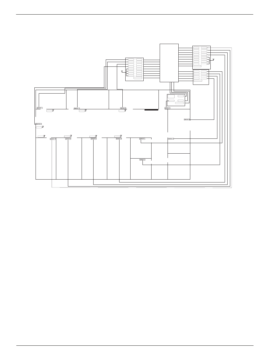
Create an interconnect wiring diagram for the system. Identify the location of each sensor An example of a
system map is shown in Figure 11. This example illustrates a system that includes multiple EA800 Multi-Zone
Environmental Alarm systems, a Winland EA400 Multi-Zone Environmental Alarm system, and a Winland
EA200 Multi-Zone Environmental Alarm system.
Figure 11 System Interconnect Wiring Diagram Example
13.
Determine the cabling required to complete the installation as indicated by the loop design, the sensors you
have selected, and the system interconnect wiring diagram.
14.
Complete the System Configuration section on the copy of the System Configuration Record you made. See
System Configuration for a description of each system level parameter.
When you have completed the previous steps you are ready to proceed to physically install the EA800 base unit
and its associated sensors using the documentation you have just created.
Sensor 5
Sensor 7
Sensor 8
Relay 1
Output 1
Output 2
Relay 2
Output 3
Relay 3
Output 4
Relay 4
Output 5
Relay 5
Output 6
Relay 6
Output 7
Relay 7
Output 8
Relay 8
EA800 No. 1
Aux Output
Alarm Panel
Sensor 5
Sensor 6
Sensor 7
Sensor 8
Relay 1
Output 1
Output 2
Relay 2
Output 3
Relay 3
Output 4
Relay 4
Output 5
Relay 5
Output 6
Relay 6
Output 7
Relay 7
Output 8
Relay 8
EA800 No. 2
Aux Output
Computer
Room
Rear
Entry
Front
Entry
Front Desk
Men's Room
Women's Room
Conference Room
Alarm panel
installation area
Ch1
Ch2
Sensor 6
Ch1
Ch1
Ch1
Ch1
Ch2
Ch2
Ch2
Ch2
Zone 1
Output 1
Output 2
Zone 2
Output 3
Zone 3
Output 4
Zone 4
EA400
Aux Output
Internal
Sensor
Output 1
Output 2
Zone 1
EA200
Aux Output
Cooler1
Cooler 2
Storage Room 3
Freezer 1
Freezer 2
Room 1
Room 2