Access control and passwords – Enviro EA800 User Manual
Page 12
8
D-011-0152
Access Control and Passwords
Access Control and Passwords
The EA800 base unit is normally locked to prevent unauthorized use. The currently active function of the F1 soft
key (
UNLOCK or LOCK) is displayed above the key. The locked and unlocked states are described below.
Note: The base unit locks automatically after 30 minutes of inactivity if the user does not press the
LOCK soft
key (F1).
■
Locked: This is the default state and limits access to the EA800 to viewing only.
UNLOCK is displayed above the F1 soft key indicates that the base unit is
currently locked. Pressing the F1 soft key prompts the user to enter a password
to unlock the base unit, permitting full access to all screens and functions. The
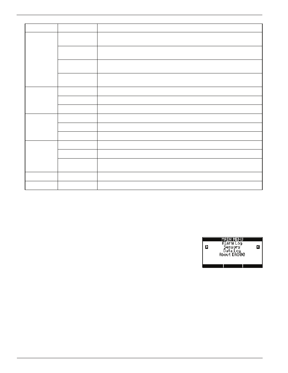
HOME key, MENU key, and the
MAIN MENU options shown on the screen at right
are available to the user when the base unit is locked.
■
Unlocked: When the base unit is unlocked,
LOCK displayed above the F1 soft key, and all information,
programming, and maintenance screens may be viewed and programming changes may be made. Pressing
the F1 soft key locks the EA800 base unit and protects it from unauthorized or unintended programming
changes, log downloads, and firmware uploads.
The base unit allows the use of two passwords for unlocking:
■
The factory default password is 0800. This password cannot be changed or deleted.
■
A second, optional password may be set by the user. To create a second user password, see “Changing the
Password” on page 63.
J6
INPUT 1
Wired input for Relay 1 external temperature, water, 4-20mA, contact closure,
or humidity sensor.
INPUT 2
Wired input for Relay 2 external temperature, water, 4-20mA, contact closure,
or humidity sensor.
INPUT 3
Wired input for Relay 3 external temperature, water, 4-20mA, contact closure,
or humidity sensor.
INPUT 4
Wired input for Relay 4 external temperature, water, 4-20mA, contact closure,
or humidity sensor.
J8
OUTPUT 1
Form C relay alarm output for Relay 1.
OUTPUT 2
Form C relay alarm output for Relay 2.
OUTPUT 3
Form C relay alarm output for Relay 3.
J9
OUTPUT 4
Form C relay alarm output for Relay 4.
OUTPUT 5
Form C relay alarm output for Relay 5.
OUTPUT 6
Form C relay alarm output for Relay 6.
J10
OUTPUT 7
Form C relay alarm output for Relay 7.
OUTPUT 8
Form C relay alarm output for Relay 8.
AUX OUT
Form C relay output that activates upon an alarm from any of the relays
(Relay 1 through Relay 8).
J13
Antenna
RF receive and transmit
J14
Antenna
RF receive and transmit
Table 3
EA800 Base Unit Connector Functions — continued
Connector
Designation
Function