0 installation – Magnum Energy MMS-E Series User Manual
Page 22
© 2011 Magnum Energy, Inc.
2.0 Installation
15
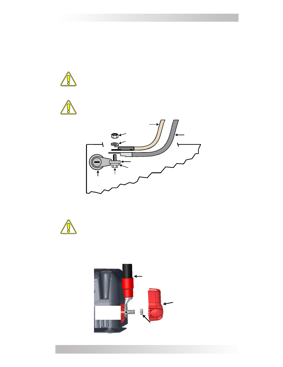
Figure 2-4, DC Cable to Battery Terminals
2.5.4 DC Cable Connections
When connecting the DC cable to the battery or to the inverter’s DC
terminals, the hardware should be installed in the correct order to
prevent high resistance connections from heating up and possibly
melting. Refer to Figures 2-4 and 2-5 to stack the hardware correctly.
Tighten the terminal connections from 13.6 to 16.3 N-m.
CAUTION: Do not put anything between the DC cable ring lug
and the battery terminal post or the inverter’s DC terminal. If
antioxidant grease or spray is used, apply after all connections
have been made and are properly tightened.
CAUTION: Overtightening or mis-threading nuts on the DC
terminals will cause the bolts to strip and snap/break-off.
CAUTION: The inverter is NOT reverse polarity protected
(negative and positive connected backwards). You must
verify the correct voltage polarity BEFORE connecting the
DC wires or damage may occur.
Crimped and sealed copper ring terminal lugs with a 5/16” hole should
be used to connect the DC wires to the inverter’s DC terminals.
Figure 2-5, DC Cable to Inverter’s DC Terminals
BATTERY
DC cable
with ring lug
bolt
flat washer
nut
lock washer
battery
post
battery terminal
Temperature sensor
Ensure the DC cable lugs are
flush with the battery terminals.
Torque the battery terminals
from 13.6 to 16.3 N-m.
DC cable
with ring lug
DC
terminal
cover
(snaps on)
Inverter’s
DC
terminal
5/16
” Flange nut or Kep
nut (with Star washer)