Magnum Energy MMS-E Series User Manual
Page 20
© 2011 Magnum Energy, Inc.
2.0 Installation
13
Info: The DC wires must be color coded with colored
tape or heat shrink tubing; BROWN for positive (+),
BLUE for negative (-), and GREEN w/ YELLOW stripe for
DC ground.
The DC wires must have either soldered and crimped lugs, crimped
copper compression lugs, or aluminum mechanical lugs. Soldered
connections alone are not acceptable for this application.
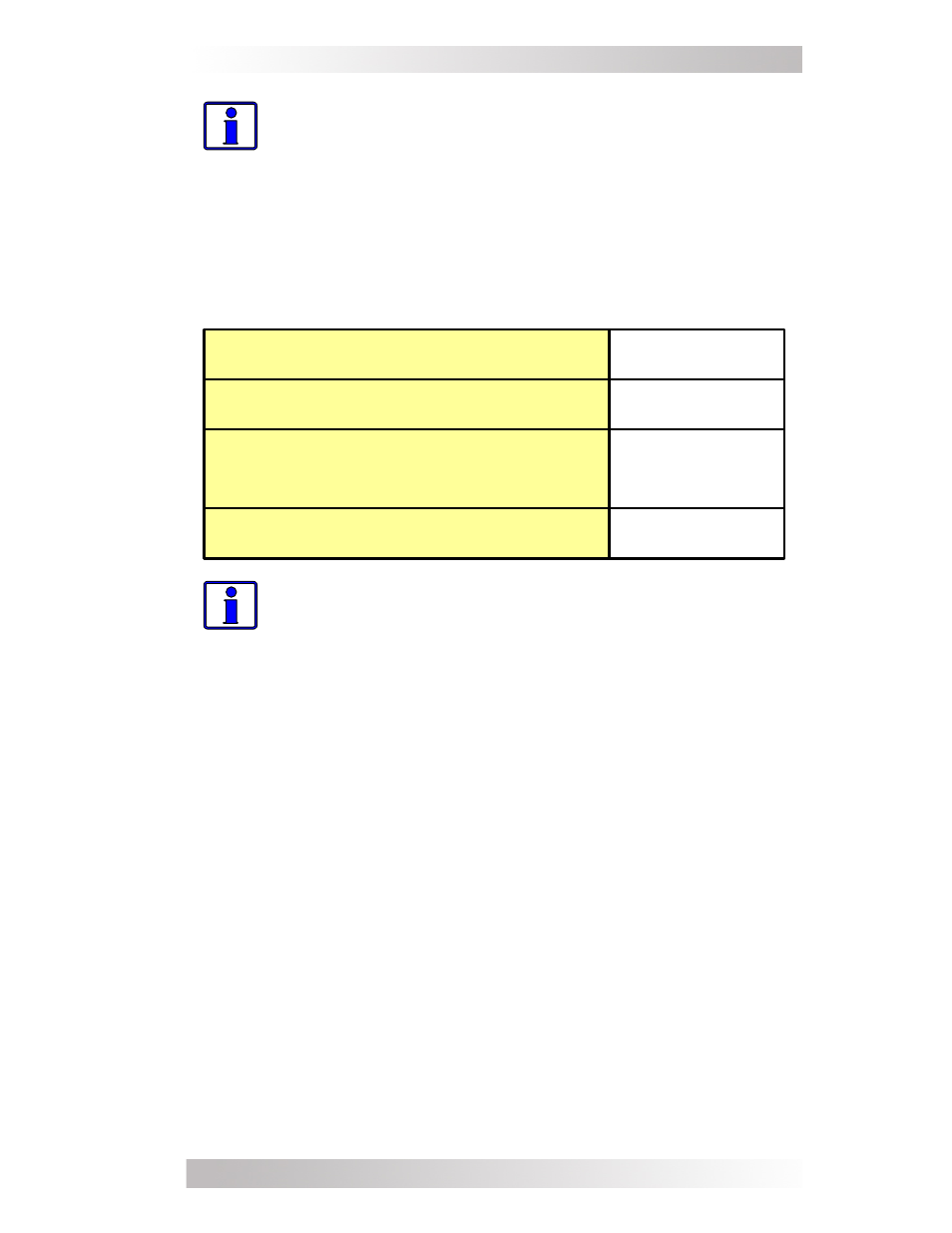
133 amps
13.29 mm²
(#6 AWG)
42.39 mm²
(#1 AWG)
[150 amps]
150 amps w/
time delay
Maximum Continuous Current
1
DC Grounding Electrode Wire Size
2
Minimum DC Wire Size
3
(90° C rating in free air)
Maximum DC Fuse Size
4
Info: The term “in free air” is defi ned as not encased in
conduit or raceway.
If the inverter is expected to operate at a distance greater than three
feet from the battery bank, the DC wire size needs to be increased to
overcome the increase in resistance – which affects the performance
of the inverter. Continue to use the overcurrent device and the DC
ground wire previously determined from Table 2-1, and then refer
to Table 2-2 to determine the minimum DC wire size you need for
various distances based on your inverter model.
Note 1 - Maximum Continuous Current is based on the inverter’s
continuous power rating when at the lowest input voltage with an
ineffi ciency factor.
Note 2 - Per standard practice, the DC grounding electrode conduc-
tor can be a 13.29 mm² (#6 AWG) conductor if that is the only con-
nection to the grounding electrode and that grounding electrode is
either a pipe, rod, or plate electrode.
Note 3 - Wire size is based on the requirements needed to increase
effi ciency and reduce stress to the inverter.
Note 4 - The next larger standard size overcurrent device may be
used if the de-rated cable ampacity falls between the standard over-
current devices found in the IEC.
Table 2-1, Recommended DC Wire/Overcurrent Device